
The I2C Advantage for Microcontroller Displays
When building embedded systems, pin conservation is critical. Parallel interfaces consume a massive amount of GPIO pins, which is why integrating a display Arduino I2C setup remains the gold standard for DIY electronics and prototyping in 2026. By utilizing the Inter-Integrated Circuit (I2C) protocol, you can drive complex visual outputs using only two wires: SDA (data) and SCL (clock). On standard 5V Arduino boards like the Uno or Nano, these map to pins A4 and A5, leaving your digital and PWM pins free for sensors and motor control.
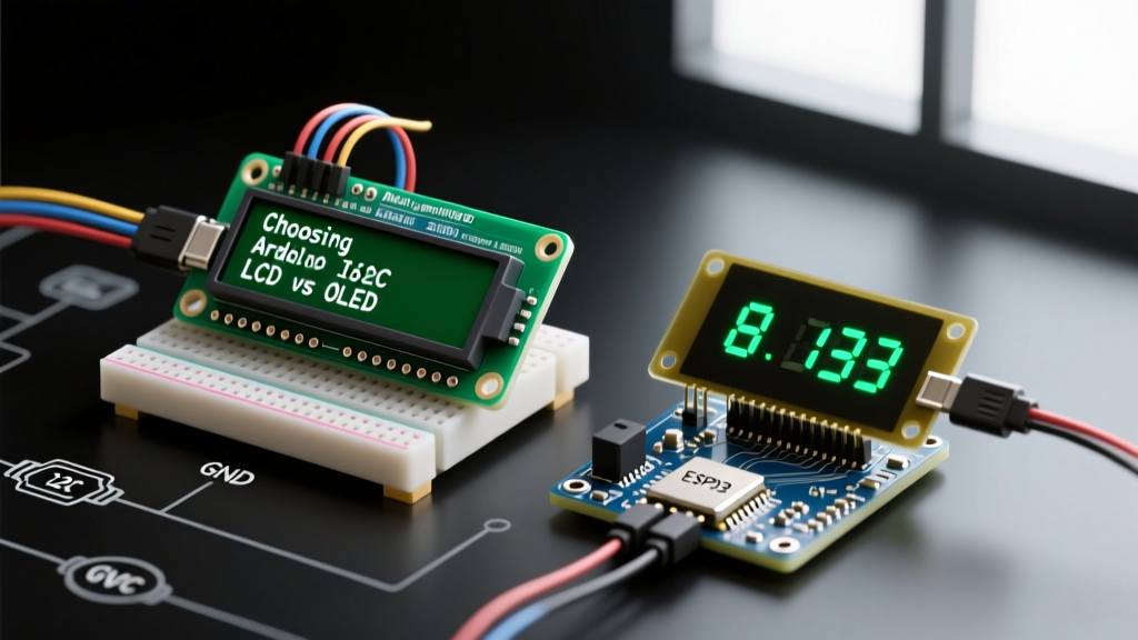
However, the market is flooded with I2C display modules, primarily split into two dominant camps: Character LCDs with I2C backpacks and Graphic OLEDs. Choosing the right one depends on your project's power budget, environmental conditions, and UI complexity. In this component comparison, we break down the hardware architectures, real-world pricing, and specific failure modes of the most popular I2C displays available today.
Contender 1: 16x2 and 20x4 I2C Character LCDs
The classic HD44780-based character LCD has been a staple in electronics for decades. To make them I2C-compatible, manufacturers solder a PCF8574 I2C expander backpack onto the 16-pin header. This translates the I2C serial data into the parallel signals the HD44780 controller requires.
Hardware Specifics and Pricing
As of 2026, a standard 16x2 I2C LCD (blue backlight, white text) costs between $3.50 and $5.00 from generic suppliers, while the larger 20x4 variant ranges from $6.00 to $8.50. They require a 5V power supply and typically draw around 20mA to 30mA, largely due to the always-on LED backlight.
The Addressing Trap: PCF8574T vs. PCF8574AT
One of the most common points of failure for beginners is I2C address conflicts. According to the NXP PCF8574 I2C Expander Datasheet, the base address depends on the specific chip variant used on the backpack:
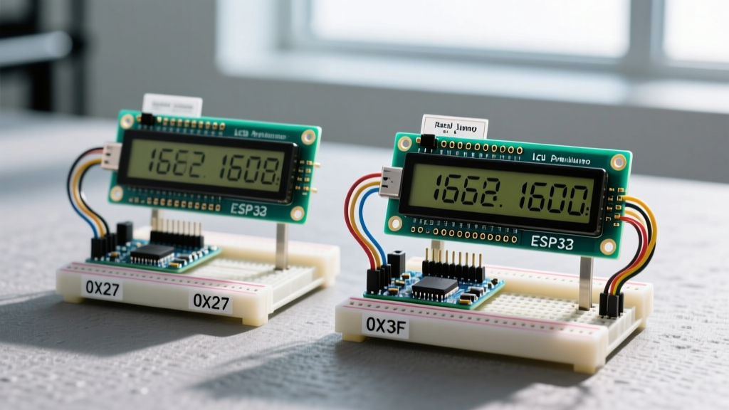
- PCF8574T: Base address is 0x20. With A0, A1, and A2 jumper pads left open (pulled high), the default address is usually 0x27.
- PCF8574AT: Base address is 0x38. With the same open jumpers, the default address shifts to 0x3F.
If your LCD remains blank and your I2C scanner sketch returns no results, you are likely initializing the wrong address in your LiquidCrystal_I2C library. Always run an I2C scanner script before hardcoding addresses in your production firmware.
Contender 2: 0.96-inch and 1.3-inch I2C OLEDs
Organic Light Emitting Diode (OLED) displays offer pixel-level addressability, allowing for custom graphics, dynamic charts, and varied fonts. The 0.96-inch (128x64 pixels) and 1.3-inch (128x64 pixels) modules are the most ubiquitous I2C OLEDs in the Arduino ecosystem.
Driver ICs: SSD1306 vs. SH1106
The 0.96-inch displays are almost universally driven by the SSD1306 controller, while the slightly larger 1.3-inch modules typically use the SH1106. While they share similar command sets, they are not perfectly interchangeable in software. The SH1106 has an internal RAM of 132x64, meaning it maps the 128x64 display with a 2-pixel horizontal offset. If you use an SSD1306 library on an SH1106 display, your graphics will appear shifted two pixels to the right, and the left edge may show visual noise.
Power Consumption and Logic Levels
Unlike LCDs, OLEDs do not require a backlight. Power draw is entirely dependent on how many pixels are illuminated. A dark screen with minimal white text might draw only 5mA, while a fully white screen can spike to 20mA or more. Pricing for generic 0.96-inch I2C OLEDs has stabilized around $4.00 to $5.50 in 2026.
Expert Warning: Many generic I2C OLEDs are labeled as '5V compatible' on the silkscreen, but they lack an onboard 3.3V voltage regulator. Feeding them 5V on the VCC pin will degrade the organic compounds rapidly, leading to permanent burn-in or total failure within weeks. Always power the VCC pin with 3.3V, even if the SDA/SCL lines are pulled up to 5V.
Head-to-Head Comparison Matrix
To help you select the right component for your next build, here is a direct comparison of the two dominant I2C display architectures.
| Feature | 16x2 I2C Character LCD | 0.96" I2C OLED (SSD1306) |
|---|---|---|
| Controller IC | HD44780 + PCF8574 Backpack | Solomon Systech SSD1306 |
| Default I2C Address | 0x27 or 0x3F | 0x3C or 0x3D |
| Resolution | 16x2 or 20x4 Characters | 128x64 Pixels |
| Typical Power Draw | 20mA - 30mA (Backlight dependent) | 5mA - 20mA (Pixel dependent) |
| Operating Voltage | 5V (Strict) | 3.3V (VCC), 5V tolerant I/O (usually) |
| 2026 Avg. Price | $3.50 - $5.00 | $4.00 - $5.50 |
| Best Arduino Library | LiquidCrystal_I2C |
Adafruit_SSD1306 / U8g2 |
| Outdoor Visibility | Poor (unless reflective/transflective) | Excellent (High contrast ratio) |
Hardware Design: I2C Bus Capacitance and Pull-Up Resistors
When wiring your display Arduino I2C setup, you must respect the physical limitations of the I2C bus. According to the Arduino Wire Library Documentation and the official I2C specification, the bus has a maximum capacitance limit of 400pF. Every wire, breadboard contact, and display module adds parasitic capacitance to the SDA and SCL lines.
Solving Signal Degradation
If you are daisy-chaining an I2C OLED, a BME280 sensor, and an I2C LCD on the same bus using long jumper wires, the capacitance will exceed 400pF. This causes the square waves of the I2C clock to round off, resulting in missed ACK bits and frozen microcontrollers.
- Standard Setup (Short wires, 1-2 devices): The internal pull-up resistors of the ATmega328P (approx. 20kΩ to 50kΩ) or the 4.7kΩ resistors on the display modules are sufficient for 100kHz operation.
- High-Speed / Long Wire Setup: If you increase the bus speed to 400kHz (Fast Mode) or use cables longer than 30cm, you must add external 2.2kΩ pull-up resistors to both SDA and SCL lines, tied to the logic voltage (3.3V or 5V). This provides a stronger current source to charge the parasitic capacitance faster, restoring crisp square waves.
Real-World Troubleshooting and Edge Cases
Even with perfect wiring, I2C displays present unique edge cases in the field. Here is how to diagnose the most common hardware and software failures.
1. The 'Blank Screen' OLED Failure
You upload your sketch, but the OLED remains completely black. First, verify the VCC voltage. As noted by the Adafruit Monochrome OLED Breakouts Guide, many clone boards route VCC directly to the OLED driver without regulation. If your multimeter reads 5V on the VCC pin and the screen is dead, the internal charge pump may have failed. Second, check the I2C address. While 0x3C is standard, some 1.3-inch SH1106 modules ship hardcoded to 0x78 (which is 0x3C shifted left by one bit to account for the R/W bit). Ensure your library expects the 7-bit address format.
2. The 'Garbage Characters' LCD Issue
If your 16x2 LCD lights up but displays solid black blocks or random Japanese characters, the issue is rarely the I2C connection. Instead, it is almost always the contrast potentiometer on the back of the PCF8574 backpack. Use a small Phillips head screwdriver to turn the blue potentiometer. If turning it all the way to either extreme does not clear the blocks, the solder joints connecting the backpack to the HD44780 PCB may have micro-fractures from mechanical stress. Reflowing the 16 header pins with a soldering iron set to 320°C for 2 seconds per pin resolves this 90% of the time.
3. Display Flickering During Motor Operations
If your I2C display flickers or resets exactly when a relay triggers or a DC motor spins, you are experiencing voltage sag and EMI (Electromagnetic Interference). I2C is highly susceptible to noise because it relies on open-drain lines. To fix this, route your display I2C wires away from motor power lines, add a 100µF electrolytic capacitor directly across the display's VCC and GND pins to handle transient current spikes, and ensure your motor flyback diodes are correctly oriented.
Final Verdict: Which Should You Choose?
If your 2026 project requires displaying static telemetry, simple sensor readings, or menu systems in well-lit indoor environments, the 16x2 or 20x4 I2C Character LCD is the most cost-effective and robust choice. It is virtually immune to burn-in and incredibly easy to read from a distance.
However, if you are building a wearable device, a battery-powered remote sensor where every milliamp counts, or a UI that requires custom icons, graphs, and dynamic animations, the 0.96-inch I2C OLED is vastly superior. Just remember to respect the 3.3V VCC requirement and manage your I2C bus capacitance to ensure reliable, long-term operation.