
The Baseline: How to Connect Servo to Arduino
Integrating RC servos into microcontroller projects is a rite of passage for embedded systems engineers and DIYers. However, while the basic premise of how to connect servo to Arduino hardware is straightforward, the reality of electromechanical integration is often plagued by voltage brownouts, signal jitter, and thermal shutdowns. Whether you are actuating a robotic arm with high-torque MG996R metal-gear servos or panning a camera with lightweight SG90 micro servos, understanding the underlying electrical constraints is critical.
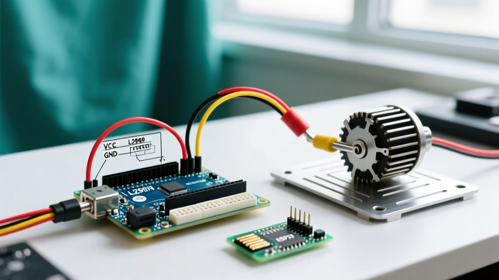
A standard hobby servo operates on a 3-wire interface:
- Ground (GND): Typically brown or black. Must share a common ground with the microcontroller.
- Power (VCC): Typically red. Requires a stable 4.8V to 6.0V DC supply.
- Signal (PWM): Typically orange, yellow, or white. Requires a 50Hz Pulse Width Modulated logic signal (3.3V or 5V tolerant).
On an Arduino Uno R3 or R4, you must route the signal wire to a hardware PWM-capable pin (marked with a tilde ~, such as pins 3, 5, 6, 9, 10, or 11). While the official Arduino Servo library can generate software PWM on any digital pin, relying on hardware timers drastically reduces CPU overhead and eliminates software-induced jitter.
Power Supply Architecture: The Root of 80% of Failures
Critical Engineering Warning: Never power an MG996R or DS3218 servo directly from the Arduino's 5V output pin. Doing so will almost certainly trigger a thermal shutdown of the onboard NCP1117 voltage regulator, causing the microcontroller to reset or the regulator to permanently fail.
The most common failure point when makers research how to connect servo to Arduino circuits is inadequate current sourcing. Microcontrollers are designed for logic-level signaling, not inductive motor driving. When a servo stalls or starts under load, it draws its maximum stall current. If your power supply cannot deliver this instantaneous current, the voltage rail sags, pulling the Arduino's logic levels below the brownout detection threshold (typically 2.7V for the ATmega328P), resulting in an immediate system reset.
Servo Stall Current vs. Arduino Limits
| Servo Model | Type | Stall Current (at 5V) | Safe Power Source |
|---|---|---|---|
| TowerPro SG90 | 9g Micro (Nylon) | ~750 mA | Arduino 5V Pin (USB limit applies) |
| TowerPro MG996R | High-Torque (Brass) | ~2.5 A | External 5V 3A BEC / Buck Converter |
| DS3218 | 20kg Digital (Steel) | ~3.0 A | External 5V 5A Step-Down Regulator |
| Arduino Uno 5V Pin | Logic/Microcontroller | 500 mA (USB) / 800mA (Barrel) | N/A (Source Limit) |
Note: Data aligns with standard RC actuator specifications outlined in the Adafruit Motor Selection Guide.
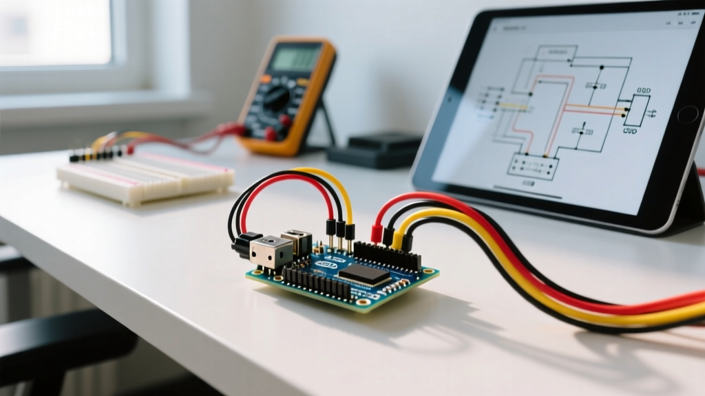
The Professional Fix: Use an external Battery Eliminator Circuit (BEC) or a buck converter like the Pololu 5V, 5A Step-Down Voltage Regulator D24V50F5 (retailing around $14 in 2026). Wire the BEC input to your main battery pack (e.g., a 2S or 3S LiPo), and route the BEC's 5V output directly to the servo's VCC. Crucially, you must tie the BEC's Ground to the Arduino's Ground. Without a common ground reference, the PWM signal will float, causing erratic servo behavior.
Troubleshooting Matrix: Symptoms, Causes, and Fixes
When your servo misbehaves, the issue is rarely the microcontroller code. Use this diagnostic matrix to isolate hardware and signal faults.
| Symptom | Root Cause Analysis | Actionable Fix |
|---|---|---|
| Arduino Resets on Servo Movement | Voltage brownout due to inductive current spike exceeding the PSU's transient response capability. | Solder a 470µF to 1000µF low-ESR electrolytic capacitor directly across the servo's VCC and GND wires to act as a local energy reservoir. |
| Random Jitter at Holding Angle | Electromagnetic interference (EMI) on the PWM signal wire, or a missing common ground reference. | Use twisted-pair wiring for Signal and GND. Ensure external PSU GND is physically bonded to Arduino GND. Keep signal wires away from AC mains or high-current DC motor lines. |
| Servo Hums/Buzzes Continuously at Rest | Analog feedback loop 'hunting' due to mechanical backlash or potentiometer noise. | Call myservo.detach() in your sketch once the target position is reached. Alternatively, upgrade to a digital servo (e.g., DS3218) which handles deadbands via internal MCU processing. |
| Servo Snaps to Random Angle on Boot | Floating PWM pin state before the Servo.attach() function initializes the hardware timer. |
Add pinMode(servoPin, OUTPUT); digitalWrite(servoPin, LOW); in your setup() block before calling Servo.attach(). |
| Servo Spins Continuously (360°) | Internal 5kΩ potentiometer wiper has lost contact (deadband), or the servo is a modified continuous-rotation variant. | Open the servo casing and clean the potentiometer track with electronic contact cleaner. If the carbon track is worn, replace the pot or the servo. |
Signal Integrity: Debugging the 50Hz PWM Waveform
If you have verified your power architecture and common grounds, but the servo still refuses to position accurately, you must inspect the PWM signal. A standard RC servo expects a 50Hz signal, meaning the total period of the waveform is exactly 20 milliseconds (ms).
- 1.0 ms pulse width: Commands the servo to 0 degrees (fully counter-clockwise).
- 1.5 ms pulse width: Commands the servo to 90 degrees (center neutral).
- 2.0 ms pulse width: Commands the servo to 180 degrees (fully clockwise).
Diagnostic Tooling: Do not rely solely on a multimeter to read PWM signals; the averaging function will yield misleading voltage readings (e.g., 0.4V to 0.6V). Instead, use a USB logic analyzer (such as a Saleae Logic clone, available for ~$15) paired with the open-source PulseView software. Hook the logic analyzer probe to the Arduino signal pin and the ground clip to the common GND. Set the trigger to the rising edge of the PWM channel. If your pulse width measures 1.42ms when your code requests 90 degrees (1.5ms), your Arduino's 16MHz crystal oscillator might be experiencing clock drift, or the Servo.h library's microsecond mapping is slightly offset for your specific servo brand. You can manually calibrate this using the attach(pin, min, max) function, passing custom microsecond boundaries (e.g., attach(9, 550, 2400)) to match the physical limits of your actuator.
Mechanical & Edge Case Failures
Electrical troubleshooting only solves half the battle. Servos are closed-loop electromechanical systems, meaning mechanical wear directly translates into electrical anomalies.
Potentiometer Deadbands and Gear Stripping
Inside an analog servo like the SG90, a 5kΩ potentiometer is geared to the output shaft. The servo's internal comparator circuit reads the voltage divider created by this potentiometer to determine the current shaft position. If the servo is subjected to heavy lateral loads, the nylon gears can strip, or the potentiometer's physical wiper can lift off the carbon track. When the wiper hits a 'deadband' (an area of infinite resistance), the internal comparator assumes the shaft is infinitely far from the target position, causing the DC motor to spin at maximum voltage until it hits a hard mechanical stop.
Preventative Maintenance:
- Avoid Side-Loading: Never mount a servo where the output shaft bears the weight of the assembly laterally. Use thrust bearings or external linkages to transfer axial loads.
- Implement Soft Starts: Instead of commanding an immediate jump from 0° to 180°, write a
forloop that increments the position by 1-degree steps with a 20msdelay(). This reduces the instantaneous current spike and mechanical shock to the gear train. - Use Mechanical Limits: If your application only requires 90° of travel, physically design your linkage to restrict movement, preventing the servo from stalling against its internal hard stops, which draws maximum current and generates destructive heat inside the winding.
Summary
Mastering how to connect servo to Arduino hardware requires looking beyond the basic three-wire diagram. By decoupling your high-current inductive loads from the microcontroller's logic power supply, ensuring a robust common ground, and utilizing proper signal diagnostics, you can eliminate 99% of the jitter, humming, and brownout issues that plague embedded robotics projects. Always design your power architecture around the servo's stall current, not its idle current, and your system will operate reliably in the field.