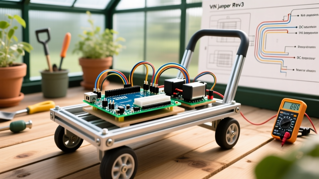

Engineering an Automated Greenhouse Cart with the Arduino Motor Shield Rev3
In the rapidly expanding sector of automated indoor agriculture in 2026, moving 50kg payloads of harvested produce across damp, uneven greenhouse floors requires a robust, high-torque mobile base. While modern brushless ESCs and CAN-bus motor controllers dominate heavy industrial AGVs, the Arduino Motor Shield Rev3 (Model: A000079) remains a highly relevant, accessible platform for prototyping and deploying light-to-medium duty automated carts. Built around the STMicroelectronics L298P dual full-bridge driver, this shield offers a unique combination of integrated current sensing and straightforward PWM control that off-the-shelf bare modules often lack.
This guide details the real-world engineering, critical hardware modifications, and thermal management strategies required to deploy the Arduino Motor Shield Rev3 in a continuous-duty greenhouse transport cart.
Anatomy and Electrical Specifications
Before wiring high-current inductive loads, it is vital to understand the physical limits of the shield. The Rev3 utilizes the L298P, a bipolar junction transistor (BJT) based dual H-bridge. Unlike modern MOSFET-based drivers, BJTs suffer from a significant forward voltage drop, which directly impacts thermal design.
| Parameter | Specification | Real-World Implication |
|---|---|---|
| Motor Driver IC | L298P (Dual Full-Bridge) | Requires ~2V to 3V headroom; generates significant heat. |
| Continuous Current per Channel | 2.0A | Peak stall currents must not exceed this for >1 second. |
| Maximum Motor Voltage (VM) | 24V DC (Shield Limit) | IC supports 46V, but shield capacitors/traces are rated lower. |
| Current Sensing Shunt | 0.15Ω per channel | Outputs analog voltage via LM358 op-amp (1.65V per Amp). |
| Control Logic Voltage | 5V | Native compatibility with ATmega328P (Uno). |
For deeper electrical characteristics, engineers should consult the official Arduino Motor Shield Rev3 Documentation and the foundational STMicroelectronics L298 Datasheet.
Real-World Build: Component Selection for a 50kg Cart
To move a 50kg cart at 0.5 meters per second on a rubberized greenhouse floor, we selected the following drivetrain components:
- Motors: Two 12V 60W DC planetary gearmotors (100 RPM, 4.5 N·m torque). Running load is ~1.2A per motor.
- Power Supply: 12V 18Ah Sealed Lead Acid (SLA) battery. SLA is preferred over LiFePO4 here for its low cost, high surge current capability, and tolerance to the high-humidity greenhouse environment.
- Microcontroller: Arduino Uno R4 Minima (provides 5V logic and enhanced ADC resolution for current sensing).
- Chassis: Laser-cut 3mm aluminum diamond plate with 4-inch pneumatic casters.
The Critical VIN Jumper Modification (Preventing Catastrophic Failure)
The most common point of failure when deploying the Arduino Motor Shield Rev3 in real-world applications is the destruction of the Arduino board's onboard voltage regulator. By default, the shield features a jumper labeled VIN that bridges the motor power supply screw terminals directly to the Arduino's VIN rail.
CRITICAL ENGINEERING WARNING: If you power the shield's screw terminals with a 24V battery pack to drive high-voltage motors, that 24V is fed directly into the Arduino Uno's linear NCP1117 5V regulator. Dropping 24V to 5V at even a modest 50mA logic draw dissipates nearly 1W of heat. This will instantly trigger thermal shutdown or cause catastrophic regulator failure.
The Fix: You must sever the VIN jumper trace on the underside of the Motor Shield using a hobby knife. Once cut, the motor power and logic power are isolated. You then supply the motors via the shield's green screw terminals (up to 24V), and power the Arduino Uno separately via its USB port or barrel jack (using a dedicated 7.5V to 9V step-down buck converter tied to the battery).
Wiring and Exploiting Integrated Current Sensing
Unlike bare TB6612FNG breakout boards, the Rev3 integrates a current-sensing shunt resistor and an LM358 operational amplifier for each channel. This allows the microcontroller to monitor motor load in real-time, enabling software-based stall detection and payload weighing.
Pinout Mapping
- Direction (DIR): Digital Pin 12 (Channel A), Digital Pin 13 (Channel B).
- PWM (Speed): Digital Pin 3 (Channel A), Digital Pin 11 (Channel B).
- Brake: Digital Pin 9 (Channel A), Digital Pin 8 (Channel B). Pull HIGH to engage dynamic braking.
- Current Sensing: Analog Pin A0 (Channel A), Analog Pin A1 (Channel B).
Software Implementation for Stall Detection
The LM358 op-amp scales the voltage across the 0.15Ω shunt resistor. At 0A, the analog read is ~0V. At 2A, it outputs 3.3V. Using the Uno R4's 14-bit ADC (0-16383), we can calculate the exact current draw to detect if the cart has collided with an obstacle or is stuck in mud.
Logic Flow:
1. Read Analog A0.
2. Map the 14-bit value (0-16383) to a 0-3.3V range.
3. Divide the voltage by 1.65 to get the exact Amperage.
4. If Amperage > 1.8A for >500ms, trigger an emergency brake and reverse sequence to clear the obstruction.
Thermal Management and Failure Modes
The L298P is a legacy bipolar design. According to the STMicroelectronics L298 Datasheet, the total saturation voltage drop across the H-bridge transistors is typically 2.0V at 1A, and can reach 3.0V at 2A.
If Channel A is driving a motor at 1.5A continuous, the power dissipated as heat on the L298P chip is calculated as: P = V_drop × I = 2.5V × 1.5A = 3.75 Watts. The Rev3 shield relies on a small, glued-on aluminum heatsink and the PCB copper pour. In a stagnant, 35°C greenhouse environment, 3.75W will push the silicon junction temperature dangerously close to the 150°C internal thermal shutdown threshold.
Thermal Mitigation Strategies
- Active Airflow: Mount a 40mm 12V brushless cooling fan directly over the L298P heatsink. This increases the convective heat transfer coefficient, allowing continuous 2A operation without thermal throttling.
- PWM Frequency Tuning: The default Arduino PWM frequency on Pins 3 and 11 is ~490Hz. Switching losses in the BJT transistors increase at higher frequencies. Keep the PWM frequency below 1kHz to minimize IC heating.
- Coast vs. Brake: When stopping the cart, use the 'coast' mode (PWM to 0, Brake to LOW) rather than dynamic braking if immediate stopping isn't required. Dynamic braking dumps the motor's kinetic energy back into the H-bridge as heat.
When to Upgrade: Rev3 vs. Modern Alternatives
While the Arduino Motor Shield Rev3 (priced around $38.00 for the official board in 2026) is excellent for prototyping and leveraging its current-sensing op-amps, production environments often demand higher efficiency. Below is a comparison against modern MOSFET-based alternatives.
| Driver Platform | Architecture | Continuous Current | Voltage Drop | Approx. 2026 Cost |
|---|---|---|---|---|
| Arduino Rev3 (L298P) | Bipolar BJT | 2.0A | ~2.5V | $38.00 (Official) |
| TI DRV8871 Breakout | NMOS H-Bridge | 3.6A | ~0.4V | $6.50 |
| Pololu VNH5019 Shield | MOSFET Half-Bridge | 12.0A | ~0.3V | $18.00 |
For a deeper look into modern low-dropout motor driving, the Texas Instruments DRV8871 Datasheet illustrates how integrated charge pumps and MOSFETs have largely eliminated the thermal penalties of older BJT designs. If your greenhouse cart payload increases beyond 50kg, migrating to a VNH5019 or dual DRV8871 setup is mandatory to prevent voltage sag and battery drain.
Expert Troubleshooting Checklist
When deploying the Rev3 shield in the field, keep this diagnostic checklist on hand for anomalous behavior:
- Motor whines but does not turn: The L298P requires a minimum motor supply voltage of ~2.5V above ground to properly bias the internal logic. Ensure your battery isn't severely depleted below the shield's minimum operating threshold.
- Arduino resets randomly during acceleration: High current draw causes a voltage dip (brownout) on the shared ground plane. Ensure your motor power ground and Arduino logic ground are tied together at a single star-ground point near the battery terminals, not relying solely on the shield's header pins.
- Current sensing reads erratic high values: The LM358 op-amp on the shield is susceptible to high-frequency EMI from the PWM switching. Implement a rolling average software filter (minimum 16 samples) in your C++ code to smooth the ADC readings.
- Shield feels hot to the touch at idle: Verify that the PWM pins are explicitly set to
0and not left in apinMode(INPUT)floating state, which can cause the H-bridge to rapidly oscillate and generate parasitic heat.
By respecting the thermal boundaries of the L298P and properly isolating the high-voltage motor rails from the sensitive 5V logic, the Arduino Motor Shield Rev3 transforms from a simple educational toy into a reliable, sensor-rich drive system for real-world automated logistics.