
The Great Soil Sensing Debate: Resistive vs. Capacitive
When building an automated irrigation system or a smart houseplant monitor, selecting the right moisture sensor Arduino module is the single most critical hardware decision you will make. The DIY electronics market is flooded with dozens of soil probes, but they almost entirely fall into two distinct technological categories: resistive and capacitive. While a beginner might grab the cheapest option available, experienced embedded engineers know that the wrong sensor topology will lead to system failure within weeks.
In this comprehensive component comparison, we break down the physics, failure modes, real-world pricing, and integration strategies for the leading soil moisture sensors available in 2026. Whether you are prototyping a quick weekend project or deploying a distributed agricultural mesh network, understanding these differences will save you from the dreaded 'zombie sensor' phenomenon.
The Core Physics: How They Measure Wetness
Before diving into specific product models, it is vital to understand the underlying electrical principles governing these sensors.
Resistive Sensors: The Conductivity Approach
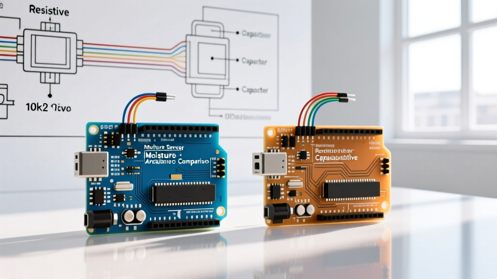
Resistive sensors operate on a simple principle: water with dissolved minerals conducts electricity. The sensor pushes a small current through two exposed metal probes and measures the voltage drop to calculate resistance. Dry soil acts as an insulator (high resistance), while wet soil acts as a conductor (low resistance). While cheap and easy to interface with an analog-to-digital converter (ADC), this method inherently passes direct current (DC) through the soil and the probe electrodes.
Capacitive Sensors: The Dielectric Approach
Capacitive sensors avoid direct electrical contact with the soil. Instead, they act as one plate of a capacitor, with the soil acting as the dielectric material. Water has a high relative permittivity (dielectric constant of ~80) compared to dry soil (~4). As soil moisture increases, the capacitance of the sensor changes. An onboard oscillator circuit converts this capacitance shift into a proportional analog voltage or digital I2C signal. Because no DC current flows through the soil, the electrodes do not degrade via electrolysis.
2026 Component Showdown: Market Leaders
Below is a direct comparison of the most popular moisture sensor Arduino modules currently dominating the market. Prices reflect average 2026 retail costs from major distributors.
| Model / Variant | Technology | Interface | Avg. Price | Expected Lifespan | Best Use Case |
|---|---|---|---|---|---|
| Generic YL-69 (LM393) | Resistive | Analog / Digital | $1.50 | 2 - 4 Weeks | Disposable science fair projects |
| Generic Capacitive v2.0 | Capacitive | Analog | $2.50 | 6 - 12 Months | Budget smart planters (with coating) |
| SparkFun SEN-13322 | Resistive (Nickel) | Analog | $7.95 | 3 - 6 Months | Short-term environmental logging |
| Adafruit STEMMA (4026) | Capacitive | I2C | $7.50 | 3+ Years | Commercial IoT & long-term deployments |
Deep Dive: Failure Modes and Edge Cases
Hardware selection is only half the battle; anticipating how your chosen sensor will fail in a harsh, wet, and chemically active environment is where true expertise lies.
The 'Zombie' Resistive Sensor
If you leave a standard YL-69 resistive probe in damp soil powered continuously, it will die a rapid, ugly death. The DC current causes electrolysis. The nickel plating on the cheap probes quickly wears away, exposing the underlying copper. The copper reacts with water and soil salts to form copper chloride—a green, crusty compound that eventually eats entirely through the trace. The sensor will either read a permanent 'dry' (open circuit) or 'wet' (short circuit) state, rendering your microcontroller's feedback loop useless.
Capacitive Drift and Salt Bridging
Capacitive sensors solve the electrolysis problem, but they introduce a new edge case: parasitic conductivity. Over time, fertilizers and hard water leave behind mineral deposits (salts) on the sensor's conformal coating. If the coating is compromised, these salts create a conductive bridge across the sensor's traces, tricking the oscillator into reading a falsely high moisture level. According to the Adafruit STEMMA Soil Sensor Guide, ensuring the integrity of the sensor's waterproofing layer is paramount for long-term accuracy in heavily fertilized soils.
Expert Wiring Strategy: The GPIO Power-Cycling Trick
The most common mistake beginners make when wiring a moisture sensor Arduino setup is connecting the sensor's VCC pin directly to the Arduino's 5V or 3.3V rail. Even if you are using a capacitive sensor, leaving it powered 24/7 accelerates degradation and drains power in battery-operated setups.
Pro Tip: Never leave a soil sensor continuously powered. Use a digital GPIO pin to supply power to the sensor only during the exact millisecond you take a reading.
Because most analog soil sensors draw less than 10mA of current, you can safely power them directly from an Arduino digital output pin (which can source up to 20mA on most AVR architectures, or 40mA absolute max). For ESP32 or low-power ARM Cortex deployments, use a small N-channel MOSFET (like the 2N7000) to switch the ground or VCC line.
Implementation Logic
- Connect the Sensor VCC to Arduino Digital Pin 8.
- Connect the Sensor GND to Arduino GND.
- Connect the Sensor Analog Out to Arduino A0.
// Power up the sensor
pinMode(8, OUTPUT);
digitalWrite(8, HIGH);

// Wait for the internal RC circuit to stabilize
delay(10);

// Take multiple samples to filter out ADC noise
int rawValue = 0;
for(int i = 0; i < 5; i++) {
  rawValue += analogRead(A0);
  delay(2);
}
rawValue = rawValue / 5;

// Immediately cut power to prevent electrochemical migration
digitalWrite(8, LOW);
This simple power-cycling routine, highlighted in the SparkFun Soil Moisture Sensor Hookup Guide, will easily triple the operational lifespan of generic capacitive modules and reduce your system's quiescent current draw to near zero.
Waterproofing the Generic v2.0 Capacitive Sensor
The generic 'v2.0' capacitive sensor (identifiable by its black solder mask and 3-pin JST connector) is a fantastic budget option at roughly $2.50. However, its factory-applied waterproofing is notoriously thin and prone to scratching during insertion into dense, rocky soils.
The Conformal Coating Protocol
To guarantee multi-year survival of the v2.0 module, you must apply your own dielectric barrier. Do not use hot glue or standard epoxy, as these can trap moisture against the PCB if the seal breaks, causing catastrophic failure. Instead, use an electronics-grade acrylic conformal coating.
- Preparation: Clean the probe with 99% isopropyl alcohol to remove manufacturing flux residues.
- Masking: Use Kapton tape to mask the top 15mm of the board (the JST connector and the top edge of the traces). Never coat the connector pins.
- Application: Apply 2-3 thin coats of MG Chemicals 419D acrylic conformal coating, or a readily available clear acrylic nail polish for budget builds.
- Curing: Allow 24 hours of curing time in a low-humidity environment before soil insertion.
This creates a robust, chemically inert dielectric barrier that maintains the capacitive fringing field while completely isolating the copper traces from soil acidity and fertilizers.
Calibration: Mapping ADC Values to Soil Reality
Raw analog readings from a moisture sensor Arduino setup are meaningless without site-specific calibration. Soil composition (clay, loam, sand, peat) drastically alters the dielectric baseline. The Arduino ADC documentation reminds us that a 10-bit ADC yields values from 0 to 1023, but sensor voltage dividers rarely span the full 0-5V range.
The 3-Point Calibration Method
- Air Dry (0% Moisture): Hold the sensor in the air. Record the analogRead() value. (Typically ~580-600 for generic capacitive v2.0).
- Field Capacity (100% Moisture): Submerge the sensor in a glass of water (up to the white line, never submerge the electronics). Record the value. (Typically ~280-300).
- Map the Range: Use the Arduino
map()function to translate these raw bounds into a clean 0-100 percentage scale.
// Example mapping for Generic Capacitive v2.0
int dryValue = 590;
int wetValue = 290;
int moisturePercent = map(rawValue, dryValue, wetValue, 0, 100);
moisturePercent = constrain(moisturePercent, 0, 100);
By performing this 3-point calibration for the exact soil mix you are using, you eliminate the guesswork and ensure your irrigation relays trigger at the precise agronomic threshold required by your plants.
Final Verdict: Which Should You Choose?
If you are building a temporary science project or a weekend prototype where budget is the only constraint, the Generic YL-69 Resistive module will suffice—provided you implement the GPIO power-cycling trick to delay its inevitable corrosion.
However, for any permanent installation, smart home integration, or agricultural deployment, capacitive sensors are the undisputed winners. For hobbyists willing to spend 10 minutes applying conformal coating, the Generic v2.0 Capacitive module offers unbeatable value. For mission-critical IoT nodes where reliability and digital I2C addressing are required, invest the $7.50 in the Adafruit STEMMA (4026). It features onboard signal conditioning, true waterproofing, and seamless integration with modern microcontrollers like the ESP32 and Raspberry Pi Pico, making it the gold standard for 2026 embedded peripheral design.