
The Diagnostic Hierarchy: Why Your Screen is Blank
There are few things more frustrating in embedded electronics than uploading a perfectly compiled sketch, seeing the backlight illuminate, and being greeted by a completely blank screen. When integrating a display in Arduino projects, the failure points span across hardware wiring, logic level mismatches, I2C address conflicts, and silent SRAM exhaustion. As of 2026, the market is flooded with ultra-cheap clone peripherals (often priced between $2.50 and $5.00) that frequently ship with undocumented pinouts or marginal voltage regulators. This guide bypasses generic advice and dives straight into the silicon-level and code-level faults that cause blank I2C LCDs, SPI OLEDs, and TFT screens.
I2C 16x2 LCDs: The 0x27 vs 0x3F Address Trap
The most common peripheral for beginners is the 16x2 character LCD equipped with an I2C backpack. If your backlight is on but no text appears, 80% of the time the issue is an I2C address mismatch or an incorrect pin mapping definition in your code.
The PCF8574 Chip Variations
The I2C backpack relies on an I/O expander chip to convert the two-wire I2C signal into the parallel data required by the HD44780 LCD controller. However, manufacturers use two different chips:
- PCF8574T: Default I2C address is usually
0x27. - PCF8574AT: Default I2C address is usually
0x3F.
If your code initializes the display at 0x27 but your board uses the 'AT' variant, the microcontroller will send data into the void. To verify your exact address, run an I2C Scanner sketch. The Adafruit I2C Scanner guide provides an excellent, reliable implementation of this diagnostic tool.
The Library Solution: Ditch LiquidCrystal_I2C
The legacy LiquidCrystal_I2C library requires you to manually map the expander pins to the LCD pins (e.g., En=2, Rw=1, Rs=0, D4=4, D5=5, D6=6, D7=7). Clone manufacturers frequently scramble these traces to save on PCB routing costs. Instead, use the hd44780 library by Bill Perry (available via the Arduino Library Manager). It utilizes the hd44780_I2Cexp class to automatically probe the I2C bus, identify the address, and auto-detect the internal pin mapping, eliminating guesswork entirely.
SPI OLEDs (SSD1306): SRAM Starvation and Pin Mapping
Monochrome 128x64 OLEDs driven by the SSD1306 controller are staples in modern DIY builds. However, a blank OLED is often a symptom of memory exhaustion rather than a wiring fault.
The 1024-Byte SRAM Bottleneck
To render graphics or text, the display requires a local framebuffer. A 128x64 monochrome display requires exactly 1,024 bytes of SRAM (128 * 64 / 8). The ATmega328P (used in the Arduino Uno and Nano) only has 2,048 bytes of total SRAM. Once you factor in the bootloader, serial buffers, and global variables, initializing the display buffer can silently fail or cause the microcontroller to reset endlessly if it exceeds available memory.
Pro Tip: If your serial monitor shows garbled output or the board continuously reboots right after calling
display.display(), you have hit the SRAM wall. Upgrade to an ATmega2560 (8KB SRAM) or an ESP32 (520KB SRAM) to resolve this.
Missing Reset Pins on Clone Modules
Many modern SSD1306 breakout boards omit the physical RST (Reset) pin to save space, exposing only VCC, GND, SCL, and SDA. If your initialization code attempts to pulse a reset pin that doesn't exist (or is mapped to an incorrect GPIO), the display controller will hang. When using the Adafruit SSD1306 library, ensure you pass -1 as the reset pin argument in the constructor if your physical board lacks the pin: Adafruit_SSD1306 display(128, 64, &Wire, -1);.
TFT Displays (ILI9341): The White Screen of Death
Color TFT screens (like the 2.4-inch ILI9341 shields or SPI breakouts) are notorious for displaying a stark, blinding white screen upon startup. This almost always indicates that the display is receiving power and the backlight is active, but the SPI initialization sequence is failing.
Parasitic Capacitance on Breadboards
SPI relies on high-speed clock signals (SCK). When prototyping on a solderless breadboard, the long jumper wires and internal metal clips introduce parasitic capacitance. At SPI clock speeds above 8 MHz, the signal degrades into a sawtooth wave, causing the ILI9341 controller to misread the initialization registers.
The Fix: Lower the SPI clock speed in your code during prototyping. In the TFT_eSPI library, drop the SPI_FREQUENCY from 40000000 down to 8000000 (8 MHz). Once you move to a soldered perfboard or custom PCB with traces under 5cm, you can safely push it back to 40 MHz.
Logic Level Shifting for 3.3V MCUs
If you are driving a 5V ILI9341 TFT shield with a 3.3V microcontroller (like the ESP32, Arduino Nano 33 IoT, or Raspberry Pi Pico), the 3.3V logic HIGH might not cross the 5V display's V_IH (Input High Voltage) threshold, which typically requires at least 3.5V to register reliably. You must use a bidirectional logic level shifter (such as the BSS138 MOSFET-based modules, costing about $1.50 in 2026) on the MOSI, SCK, CS, and DC lines.
Hardware Matrix: Common Displays & Failure Modes
| Display Type | Interface | Common Symptom | Root Cause & Fix |
|---|---|---|---|
| 16x2 LCD (HD44780) | I2C | Backlight ON, single row of solid black blocks | Contrast potentiometer on backpack is misadjusted. Use a small Phillips screwdriver to turn the blue pot until blocks disappear. |
| 128x64 OLED (SSD1306) | I2C / SPI | Screen completely dark, no backlight | Missing I2C pull-up resistors. Add 4.7kΩ resistors between SDA/SCL and VCC if your breakout board lacks them. |
| 2.4" TFT (ILI9341) | SPI | Bright white screen, no graphics | SPI clock too fast for wire length, or missing logic level shifting from 3.3V to 5V. |
| Nextion HMI | UART (Serial) | Stuck on boot logo or unresponsive | Insufficient current. Nextion displays draw up to 500mA on peaks. Power via a dedicated 5V buck converter, not the Arduino's 5V pin. |
Advanced Wiring: Pull-Up Resistors and the Wire Library
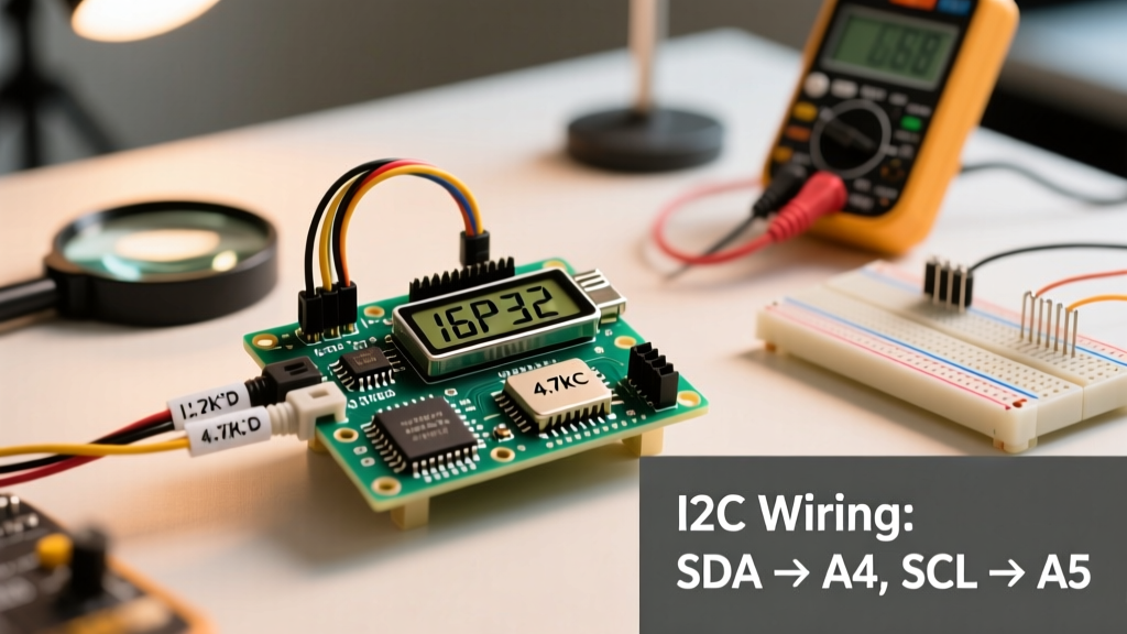
When integrating multiple I2C sensors alongside a display in Arduino circuits, the bus capacitance increases. The internal pull-up resistors on the ATmega328P (roughly 20kΩ to 50kΩ) are far too weak to pull the SDA and SCL lines HIGH fast enough when multiple devices are attached. This results in rounded I2C waveforms and intermittent display freezing.
Always install external 4.7kΩ pull-up resistors on both the SDA and SCL lines, tied to the logic voltage (3.3V or 5V, matching your MCU). For a deep dive into how the microcontroller handles these bus states, review the official Arduino Wire Library Reference, which details the underlying TWI (Two-Wire Interface) hardware buffer limits.
Final Checklist Before Blaming the Hardware
- Run I2C Scanner: Confirm the device actually acknowledges its address.
- Check VCC under load: Use a multimeter to measure the display's VCC pin while powered. A reading below 4.5V on a 5V system indicates a voltage drop from thin USB cables or inadequate breadboard power rails.
- Verify Grounds: Ensure the GND of the display, the MCU, and any external power supplies share a common ground reference.
- Isolate the Code: Strip your sketch down to a bare 'Hello World' example. If it works, your main code is likely blocking the main loop with
delay()calls, starving the display's refresh routine.
By systematically isolating the physical layer, the protocol layer, and the memory allocation layer, you can resurrect almost any stubborn display peripheral and get your project back on track.