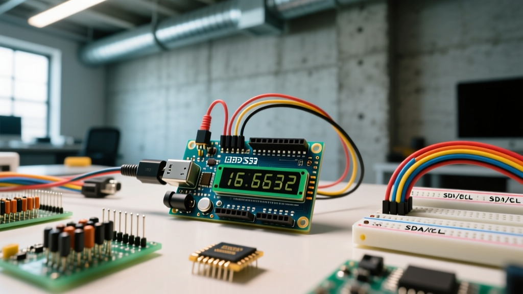

The Evolution of HMI: Why I2C Dominates Real-World Prototyping
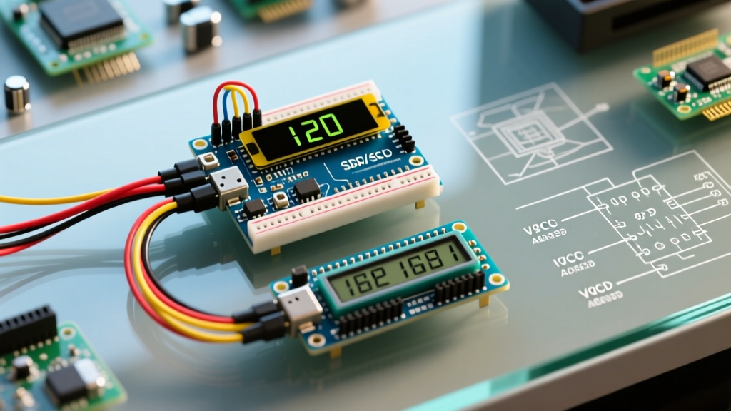
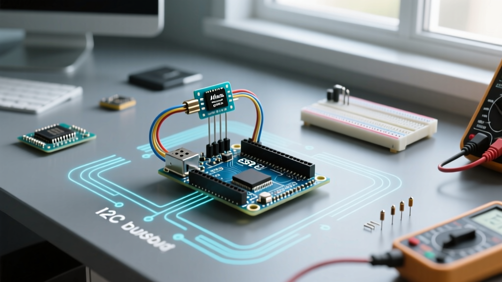
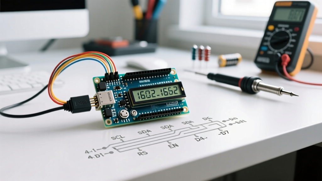
When engineers and makers build environmental monitors, industrial control panels, or IoT sensor dashboards, the interface between the microcontroller and the user is critical. Historically, wiring an Arduino to LCD screen modules required up to 16 parallel connections, consuming valuable GPIO pins and creating a rat's nest of jumper wires. Today, the industry standard for real-world prototyping relies on I2C (Inter-Integrated Circuit) backpacks. By reducing the interface to just four wires (VCC, GND, SDA, SCL), you free up pins for critical sensors like BME280 environmental arrays or DS18B20 temperature probes.
This guide moves beyond basic blink-and-print tutorials. We will explore the exact hardware specifications, real-world failure modes, and non-blocking software architectures required to connect an Arduino to LCD screen setups that survive outside the laboratory.
Hardware Bill of Materials (BOM) & 2026 Pricing
For a robust sensor dashboard in 2026, the legacy Arduino Uno R3 is no longer the optimal choice due to its limited memory and lack of native wireless capabilities. The Arduino Uno R4 WiFi (featuring the Renesas RA4M1 ARM Cortex-M4 and ESP32-S3) is the current workhorse for IoT dashboards. Pairing it with a 20x4 character LCD provides enough real estate for multi-sensor telemetry.
| Component | Specific Model / IC | Estimated 2026 Price | Role in Dashboard |
|---|---|---|---|
| Microcontroller | Arduino Uno R4 WiFi (ABX00087) | $27.50 | Core logic, Wi-Fi telemetry, sensor polling |
| Display Module | 20x4 Character LCD (HD44780 Controller) | $9.00 - $12.00 | Local HMI for real-time sensor readouts |
| I2C Backpack | PCF8574T (Address 0x27) or PCF8574AT (0x3F) | $1.50 (often pre-soldered) | Parallel-to-I2C shift register expansion |
| Logic Pull-Ups | 4.7kΩ Resistor Network (if wiring > 30cm) | $0.10 | I2C bus stabilization for long cable runs |
Step-by-Step Wiring: Arduino to LCD Screen
Connecting the Arduino to LCD screen hardware via I2C is straightforward, but logic level mismatches and bus capacitance frequently cause field failures. The Uno R4 WiFi operates at 5V logic on its primary I2C header, which perfectly matches the 5V requirement of standard HD44780 LCD modules and PCF8574 backpacks.
Pinout Matrix & Logic Level Warnings
- VCC: Connect to Arduino 5V pin. Warning: Do not power a 20x4 LCD backlight directly from the 3.3V pin; the backlight LED array requires ~4.2V to 5V and draws up to 120mA.
- GND: Connect to Arduino GND. Ensure a star-ground topology if using high-current relays nearby to prevent ground bounce.
- SDA: Connect to Arduino SDA (A4 on legacy, dedicated SDA pin on R4).
- SCL: Connect to Arduino SCL (A5 on legacy, dedicated SCL pin on R4).
Expert Insight: Logic Level Translation
If you adapt this dashboard to an ESP32 or Raspberry Pi Pico (RP2040), remember these are 3.3V logic devices. While the PCF8574 I2C backpack requires 5V for VCC to drive the LCD, its I2C data lines are pulled up to 5V via onboard resistors. Feeding 5V into a 3.3V ESP32 GPIO will degrade the silicon over time. Use a bidirectional logic level converter (like the BSS138 MOSFET circuit) between the 3.3V MCU and the 5V LCD backpack.
The Software Stack: Skipping the Address Guessing Game
The most common point of failure when wiring an Arduino to LCD screen modules is the infamous 'I2C address guess.' Older tutorials rely on the LiquidCrystal_I2C library, which requires you to manually hardcode the I2C address (usually 0x27 or 0x3F) and the exact pin mapping of the backpack. This is a fragile approach for production or field-deployed dashboards.
Instead, use the hd44780 library by Bill Perry. It is the gold standard for character LCDs. The hd44780_I2Cexp class automatically scans the I2C bus, identifies the backpack's address, and auto-detects the internal pin mapping (whether it uses the PCF8574 or PCF8574A expander chip). This eliminates 90% of software-related integration bugs.
Real-World Failure Modes & Troubleshooting
When deploying sensor dashboards in server rooms, greenhouses, or factory floors, you will encounter edge cases that bench testing misses.
1. The 'White Box' Contrast Failure
Most I2C backpacks include a blue trimpot (potentiometer) to adjust the LCD contrast (V0 pin). In high-vibration environments or areas with wide thermal cycling (e.g., an outdoor greenhouse monitor), the mechanical wiper inside the trimpot oxidizes or shifts, causing the display to wash out to solid white boxes.
The Fix: Desolder the trimpot and hardwire a voltage divider. The HD44780 V0 pin requires approximately 0.4V to 0.5V relative to VSS for optimal contrast. Solder a 1kΩ resistor from V0 to GND, and a 10kΩ resistor from V0 to VCC. This provides a rock-solid, temperature-stable contrast voltage that will never drift.
2. I2C Bus Capacitance and Signal Degradation
If your dashboard requires the LCD to be mounted on a panel door, your I2C ribbon cable might exceed 30cm. According to the official NXP I2C-bus specification, the maximum allowable bus capacitance is 400pF. Long, unshielded ribbon cables introduce parasitic capacitance that rounds off the sharp edges of the I2C square waves, causing the Arduino's Wire library to hang or drop packets.
The Fix: If your cable run exceeds 20cm, you must lower the pull-up resistor values on the I2C lines to overcome the capacitance. Replace the standard 4.7kΩ pull-ups with 2.2kΩ resistors tied to 5V. Alternatively, use a dedicated I2C bus extender IC like the P82B96 to convert the signal to a differential-like long-haul protocol.
3. Backlight Current Overdraw
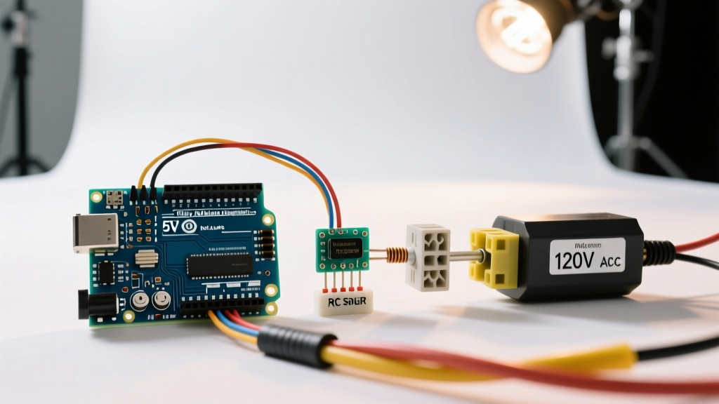
A standard 20x4 LCD backlight draws between 80mA and 120mA. The PCF8574 backpack usually includes a jumper that connects the backlight directly to the 5V rail. If you attempt to control the backlight via software by removing the jumper and driving it from an Arduino GPIO pin, you will instantly fry the microcontroller's ATmega/Renesas pin, which is typically rated for only 20mA continuous.
The Fix: Always use a logic-level N-channel MOSFET (like the 2N7000 or IRLZ44N) to switch the backlight ground path if PWM dimming or software toggling is required for power saving.
Non-Blocking Code Architecture for Sensor Dashboards
When reading slow I2C sensors (like the SCD41 CO2 sensor or BME280) and updating an LCD, using the delay() function is a fatal flaw. It blocks the microcontroller from handling Wi-Fi reconnections, button debouncing, or watchdog timers. Below is the architectural pattern for updating the Arduino to LCD screen pipeline without blocking the main loop.
Utilize the Arduino Wire library in conjunction with millis() based state machines. Separate your sensor polling rate from your LCD refresh rate. Human eyes cannot read LCD updates faster than 2-3 times per second, but your sensors might need polling every 100ms for moving-average filters.
#include <Wire.h>
#include <hd44780.h>
#include <hd44780ioClass/hd44780_I2Cexp.h>

hd44780_I2Cexp lcd;

unsigned long lastSensorPoll = 0;
unsigned long lastLCDUpdate = 0;
const int SENSOR_INTERVAL = 100;  // Poll sensors every 100ms
const int LCD_INTERVAL = 500;    // Update LCD every 500ms

void setup() {
  Wire.begin();
  lcd.begin(20, 4); // Auto-detects address and pin mapping
  lcd.print("System Initializing...");
}

void loop() {
  unsigned long currentMillis = millis();

  // Non-blocking sensor polling
  if (currentMillis - lastSensorPoll >= SENSOR_INTERVAL) {
    lastSensorPoll = currentMillis;
    readSensors(); // Custom function to read BME280, etc.
  }

  // Non-blocking LCD refresh
  if (currentMillis - lastLCDUpdate >= LCD_INTERVAL) {
    lastLCDUpdate = currentMillis;
    updateDashboard(); // Custom function to format and print to LCD
  }

  // Handle Wi-Fi and OTA updates here without delay
}
Summary
Connecting an Arduino to LCD screen hardware for real-world applications requires moving past basic tutorials. By selecting modern microcontrollers like the Uno R4, utilizing auto-detecting libraries like hd44780, and engineering out mechanical and electrical failure modes (such as trimpot drift and I2C bus capacitance), you can build sensor dashboards that are as reliable as commercial industrial HMIs. Always respect I2C electrical limits, and never drive inductive or high-current loads directly from logic pins.