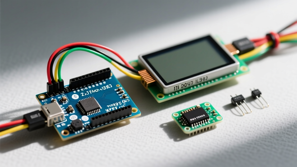

Why the ILI9341 with XPT2046 is the Maker Standard
If you are searching for a reliable touch screen for Arduino projects, the 2.8-inch ILI9341 TFT LCD paired with an XPT2046 resistive touch overlay remains the undisputed champion for beginners and professionals alike. As of 2026, these modules are widely available for $8 to $14, offering a vibrant 320x240 pixel resolution and 65K colors. Unlike capacitive screens that require complex I2C multiplexing or specialized libraries, the resistive XPT2046 controller communicates over standard SPI, making it incredibly straightforward to interface with an Arduino UNO R3, Nano, or Mega.
However, 'straightforward' does not mean 'plug-and-play.' The most common reason beginners abandon these modules is due to SPI bus contention, improper logic level shifting, and poorly configured library headers. This tutorial bypasses the generic advice and dives deep into the exact hardware wiring, voltage tolerances, and software configurations required to get your touch screen for Arduino running flawlessly on the first attempt.
Hardware Anatomy: The Dual-SPI Architecture
To successfully interface this touch screen for Arduino, you must understand that you are actually dealing with two distinct integrated circuits sharing the same physical module:
- The ILI9341 Display Controller: Handles the TFT pixel matrix. It supports high-speed SPI (up to 10MHz standard, often overclocked to 40MHz for faster frame rates).
- The XPT2046 Touch Controller: Reads the analog voltage drops across the resistive touch layers. It is a much slower chip, with a maximum stable SPI clock speed of 2MHz.
Critical Engineering Note: Because both chips share the MOSI, MISO, and SCK lines, they must have separate Chip Select (CS) pins. If you tie the Display CS and Touch CS together, the XPT2046 will inject garbage data into the display stream, resulting in screen tearing or a completely white display.
Arduino UNO R3 Wiring Matrix & Voltage Warnings
The Arduino UNO operates at 5V logic, while the ILI9341 and XPT2046 are strictly 3.3V devices. Feeding 5V directly into the SPI data pins will degrade the silicon over time and eventually destroy the touch controller. While some older 'V1.2' modules included onboard CD4050 level shifters, most modern 'V2.0' boards omit them to cut costs.
Below is the definitive wiring matrix for a safe, high-performance connection. We highly recommend using a bi-directional logic level converter (like the BSS138 MOSFET-based modules costing ~$1.50) for the SPI lines.
| Module Pin | Arduino UNO Pin | Function & Notes |
|---|---|---|
| VCC | 5V | Powers the onboard AMS1117-3.3 LDO regulator. |
| GND | GND | Common ground. Ensure thick wires to prevent touch noise. |
| CS (Display) | Pin 10 | Display Chip Select. Must be PWM-capable on some boards. |
| RESET | Pin 8 | Hardware reset for the ILI9341. |
| DC/RS | Pin 9 | Data/Command pin. Tells the screen if incoming SPI data is a pixel or a command. |
| SDI(MOSI) | Pin 11 | SPI Master Out Slave In. Use Level Shifter. |
| SDO(MISO) | Pin 12 | SPI Master In Slave Out. |
| SCK | Pin 13 | SPI Clock. Use Level Shifter. |
| T_CS (Touch) | Pin 4 | Touch Chip Select. Completely separate from Display CS. |
| T_IRQ | Pin 3 | Touch Interrupt. Pulls LOW when the screen is pressed. |
Software Setup: Configuring TFT_eSPI
For rendering graphics, the TFT_eSPI library is the industry standard. It is heavily optimized for AVR and ESP32 architectures. However, beginners often fail because they do not edit the User_Setup.h file before compiling.
Step 1: Edit User_Setup.h
Navigate to your Arduino libraries folder (Documents/Arduino/libraries/TFT_eSPI) and open User_Setup.h in a text editor. You must comment out all default drivers and uncomment the ILI9341 driver. Furthermore, you must define the exact pins we used in our wiring matrix.
// Uncomment ONLY this driver
#define ILI9341_DRIVER

// Define Arduino UNO SPI pins
#define TFT_CS   10
#define TFT_DC    9
#define TFT_RST   8
#define TFT_MOSI 11
#define TFT_MISO 12
#define TFT_SCLK 13

// Set SPI speed (Keep at 20MHz for stability without level shifters)
#define SPI_FREQUENCY  20000000
Step 2: Install the Touch Library
For the touch overlay, do not use the outdated Adafruit TouchScreen library. Instead, install the XPT2046_Touchscreen library by Paul Stoffregen via the Arduino Library Manager. It handles the 2MHz clock speed limitation natively and provides superior debouncing.
Calibrating the Touch Overlay
Resistive touch screens do not output pixel coordinates (0-320, 0-240). Instead, the XPT2046 outputs raw 12-bit ADC values ranging from roughly 200 to 3900 depending on the physical pressure and manufacturing tolerances. You must map these raw values to your screen dimensions.
Here is a robust calibration snippet that handles axis inversion and dead-zones:
#include <XPT2046_Touchscreen.h>
#define CS_PIN  4
#define TIRQ_PIN  3

XPT2046_Touchscreen ts(CS_PIN, TIRQ_PIN);

void setup() {
  Serial.begin(115200);
  ts.begin();
  ts.setRotation(1); // Match your TFT rotation
}

void loop() {
  if (ts.touched()) {
    TS_Point p = ts.getPoint();
    // Map raw XPT2046 values to 320x240 screen
    // Note: Min/Max values (250-3850) require physical testing on your specific unit
    int x = map(p.x, 250, 3850, 0, 320);
    int y = map(p.y, 3850, 250, 0, 240);

    // Constrain to prevent negative numbers or out-of-bounds errors
    x = constrain(x, 0, 320);
    y = constrain(y, 0, 240);

    Serial.print('X: '); Serial.print(x);
    Serial.print(' Y: '); Serial.println(y);
  }
}
For a deeper understanding of how the Arduino handles hardware SPI bus allocation and clock dividers, refer to the official Arduino SPI Communication Guide.
Real-World Troubleshooting & Edge Cases
Even with perfect wiring, environmental and electrical factors can cause erratic behavior. Here is how to diagnose the three most common failure modes when integrating a touch screen for Arduino.
1. The 'White Screen of Death'
Symptom: The backlight turns on, but the display is entirely white. No graphics render.
Root Cause: The ILI9341 initialization sequence failed. This is almost always caused by the DC (Data/Command) pin being wired incorrectly, or the SPI clock speed being set too high in User_Setup.h for the Arduino UNO's 16MHz ATmega328P to handle reliably.
Fix: Drop SPI_FREQUENCY to 10000000 (10MHz) and verify the DC pin is not sharing a timer with a PWM function that might be interrupting the signal.
2. Touch Dropouts and 'Ghost' Presses
Symptom: The screen registers touches when you aren't pressing it, or drops valid presses.
Root Cause: SPI bus contention. The TFT_eSPI library pushes data at 20MHz+, but the XPT2046 touch controller maxes out at 2MHz. If the touch CS pin is not properly pulled HIGH via a 10kΩ resistor when idle, the high-speed display clock will induce crosstalk in the touch controller's MISO line.
Fix: Solder a 10kΩ pull-up resistor between the XPT2046 T_CS pin and the 3.3V line on the module. Alternatively, move the touch controller to a Software SPI bus using the XPT2046_Touchscreen alternate constructor.
3. Inverted or Mirrored Touch Axes
Symptom: Pressing the top-left registers as the bottom-right.
Root Cause: The physical orientation of the touch layer does not match the software rotation of the TFT matrix.
Fix: Do not rewrite your mapping math. Simply use ts.setRotation(1); (or 0, 2, 3) in your setup function until the physical orientation matches the software output. Always call tft.setRotation() and ts.setRotation() with the exact same integer.
Summary
Integrating an ILI9341 touch screen for Arduino is a rite of passage for embedded hobbyists. By respecting the 3.3V logic limits, separating the Chip Select lines, and properly configuring the TFT_eSPI header files, you transform a frustrating $10 piece of glass into a powerful, responsive human-machine interface. Whether you are building a smart thermostat, a custom macro-keyboard, or a portable sensor dashboard, mastering this dual-SPI architecture lays the groundwork for advanced peripheral interfacing.