
The Anatomy of a MAX7219 LED Matrix Arduino Setup
Building a custom scoreboard, scrolling ticker, or retro pixel-art display requires a reliable, low-latency interface. In 2026, the combination of an LED matrix Arduino setup driven by the MAX7219 IC remains the gold standard for DIY electronics and prototyping. Unlike raw LED multiplexing—which consumes dozens of GPIO pins and hogs CPU cycles with interrupt timers—the MAX7219 handles all multiplexing, constant-current driving, and refresh rates internally via a simple Serial Peripheral Interface (SPI).
The most ubiquitous module on the market is the FC-113, which pairs the MAX7219CWG driver IC with a 1088AS 8x8 dot matrix display. Generic imports typically cost between $1.20 and $2.50 per unit, while premium variants from brands like Adafruit or SparkFun (which include onboard level shifters for 3.3V logic compatibility) range from $8.00 to $12.00. This guide focuses on wiring, power delivery, and coding the standard 5V FC-113 module using hardware SPI.
Hardware SPI Wiring Matrix
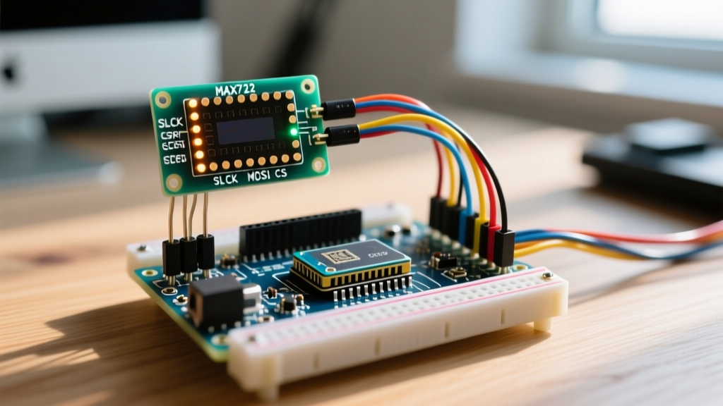
Communicating with the MAX7219 requires only three data pins alongside power and ground. While software SPI (bit-banging) is possible, utilizing the Arduino's dedicated hardware SPI bus ensures maximum throughput and prevents display tearing during complex animations.
| MAX7219 Pin | Arduino UNO / Nano (ATmega328P) | Arduino Mega 2560 | Function |
|---|---|---|---|
| VCC | 5V (See Power Warning) | 5V (See Power Warning) | Logic and LED Power (4.0V - 5.5V) |
| GND | GND | GND | Common Ground Reference |
| DIN | Pin 11 (MOSI) | Pin 51 (MOSI) | Data In (SPI Master Out Slave In) |
| CS | Pin 10 (SS) | Pin 53 (SS) | Chip Select (Active Low) |
| CLK | Pin 13 (SCK) | Pin 52 (SCK) | Clock Signal (SPI Clock) |
Critical Hardware Note: Many budget FC-113 modules omit the 100nF decoupling capacitor across the VCC and GND pins of the MAX7219 IC. According to the Analog Devices MAX7219 Datasheet, this capacitor is mandatory to filter high-frequency switching noise. If your module lacks it, solder a 0.1µF ceramic capacitor directly across the VCC and GND pins on the PCB to prevent erratic Arduino resets.
Power Delivery: Avoiding the Brownout Trap
The most common point of failure in LED matrix Arduino projects is inadequate power delivery. An 8x8 matrix contains 64 LEDs. While the MAX7219 multiplexes the display (illuminating only one row at a time, resulting in a 1/8th duty cycle), the instantaneous current draw during peak white illumination can exceed 300mA per module.
Current Calculation and Supply Sizing
- Single Module (8x8): Peak ~350mA. Can safely be powered via the Arduino UNO's 5V USB rail (which typically supports up to 500mA via a standard PC USB port).
- Cascaded 4-Module Array (32x8): Peak ~1.4A. Do not power this through the Arduino's 5V pin. The onboard linear voltage regulator and PCB traces will overheat, leading to brownouts and permanent trace damage.
- Recommended Solution: Use a dedicated 5V 2A (or higher) buck converter or bench supply. Wire the external 5V and GND directly to the matrix module's input terminals, ensuring the external GND is tied to the Arduino's GND to establish a common logic reference.
Programming the Display with MD_MAX72XX
Forget the outdated LedControl library. For modern 2026 development, the industry standard is the Arduino SPI ecosystem paired with the MD_MAX72XX library by MajicDesigns. It supports hardware SPI, cascading, and complex sprite rendering with minimal memory overhead.
Step-by-Step Code Implementation
Install the MD_MAX72XX library via the Arduino Library Manager. The following code initializes a single 8x8 matrix, draws a custom heart sprite, and demonstrates hardware SPI configuration.
#include <MD_MAX72xx.h>
#include <SPI.h>

// Hardware SPI pins (Arduino UNO)
#define CS_PIN 10
#define MAX_DEVICES 1 // Number of cascaded modules

// Create the display object using Hardware SPI
MD_MAX72XX mx = MD_MAX72XX(MD_MAX72XX::FC16_HW, CS_PIN, MAX_DEVICES);

// 8x8 Heart Sprite (Binary representation)
const uint8_t heart_sprite[] = {
  0b00000000,
  0b00011000,
  0b00111100,
  0b01111110,
  0b01111110,
  0b00111100,
  0b00011000,
  0b00000000
};

void setup() {
  mx.begin();
  mx.control(MD_MAX72XX::INTENSITY, 5); // Set brightness (0-15)
  mx.clear();
}

void loop() {
  // Draw the sprite at column 0, row 0
  mx.setBuffer(0, 8, heart_sprite);
  delay(1000);

  mx.clear();
  delay(500);
}
Advanced Configuration: The RSET Resistor
The brightness and segment current of your LED matrix Arduino display are not controlled solely by software; they are fundamentally limited by the physical RSET resistor connected to Pin 18 of the MAX7219 IC. The SparkFun SPI Tutorial notes that understanding hardware-level SPI and driver limits is crucial for peripheral longevity.
The formula to determine the segment current ($I_{SEG}$) is:
$I_{SEG} = \frac{V_{CC} \times 300}{R_{SET}}$
Most generic modules ship with a 10kΩ resistor. Assuming a 5V VCC: $I_{SEG} = \frac{5 \times 300}{10000} = 15mA$ per segment. If your display appears too dim, you can safely swap the 10kΩ SMD resistor for a 4.7kΩ resistor, pushing the current to ~32mA. Warning: Never exceed 40mA per segment, or you will permanently degrade the 1088AS LED matrix phosphors.
Diagnostic Troubleshooting Matrix
When integrating SPI peripherals, edge cases inevitably arise. Use this diagnostic table to resolve common hardware and software anomalies.
| Symptom | Root Cause Analysis | Actionable Fix |
|---|---|---|
| Random Flickering / Reset | USB port current limit exceeded; VCC dropping below 4.0V during high-white frames. | Switch to a dedicated 5V 2A external power supply. Add 100µF bulk capacitor at module input. |
| Ghosting (Dim LEDs in 'Off' State) | SPI Clock speed too high for the breadboard parasitic capacitance, causing signal bounce. | Lower SPI clock divider in code, or shorten jumper wires to under 10cm. Solder direct connections. |
| Scrolling Text Backwards | Incorrect hardware type defined in MD_MAX72XX constructor (e.g., using FC16_HW on an ICStation module). | Change MD_MAX72XX::FC16_HW to MD_MAX72XX::GENERIC_HW or ICSTATION_HW in the setup declaration. |
| Only First Module Lights Up | DOUT to DIN daisy-chain connection broken or missing common ground between cascaded modules. | Verify DOUT of Module 1 connects strictly to DIN of Module 2. Ensure all VCC/GND rails are continuous. |
Final Integration Tips
For permanent installations, abandon breadboards entirely. The high-frequency switching of the SPI clock (often running at 4MHz to 8MHz) is highly susceptible to electromagnetic interference (EMI) and parasitic capacitance on long, unshielded jumper wires. Use a custom PCB or perfboard with ground planes to ensure your LED matrix Arduino project survives long-term deployment without signal degradation.