
Beyond the Sweep Example: Real-World Servo Integration
Most engineers and hobbyists begin their robotics journey with the default Sweep example provided in the IDE. While this is an excellent proof-of-concept, deploying the servo library arduino ecosystem into real-world automation—such as camera gimbals, automated fluid valves, or multi-axis robotic arms—reveals severe hardware and software limitations that basic tutorials ignore. In 2026, while modern microcontrollers like the ESP32 and RP2040 dominate new designs, the ATmega328P (found in the Uno and Nano) remains a staple for low-cost industrial peripherals and legacy retrofits. Understanding the deep mechanics of servo control, power delivery, and timer conflicts is mandatory for building reliable, jitter-free electromechanical systems.
The Hidden Limitations: Timer1 and PWM Conflicts
The standard Arduino Official Servo Library Reference achieves precise 50Hz PWM signals by hijacking Timer1 on 8-bit AVR microcontrollers. While this guarantees the strict 1-2ms pulse width required by standard RC servos, it comes with a hidden cost: Timer1 controls hardware PWM on Pins 9 and 10.
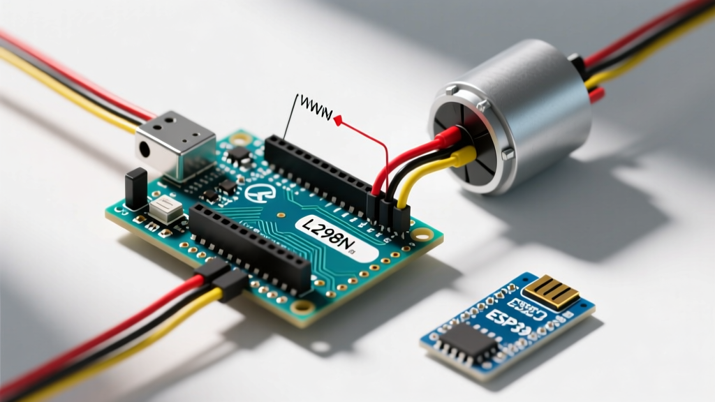
In a real-world automation scenario, you might need to drive a DC motor via an L298N or DRV8871 H-bridge, or dim high-power indicator LEDs using analogWrite(). If you attempt to use analogWrite() on pins 9 or 10 after attaching a servo, the hardware PWM is disabled, and the pins default to a crude software-based fallback or fail entirely. Actionable Fix: Always map your DC motor speed control or LED dimming to pins 3, 5, 6, or 11 (controlled by Timer0 and Timer2) when utilizing the default servo library on an ATmega328P.
Hardware Selection Matrix for Industrial Automation
Choosing the wrong servo for an industrial application leads to stripped gears, thermal shutdowns, and positional drift. Below is a comparative matrix of standard and high-torque servos frequently used in automated systems, reflecting current market availability and pricing in 2026.
| Servo Model | Torque (at 6V) | Peak Stall Current | Price Range (2026) | Best Real-World Application |
|---|---|---|---|---|
| TowerPro SG90 | 1.8 kg/cm | ~650mA | $2.00 - $4.00 | Pan/Tilt sensors, lightweight latches |
| TowerPro MG996R | 13 kg/cm | ~2.5A | $8.00 - $12.00 | Robotic arms, heavy-duty fluid valves |
| DS3218 (20kg) | 20 kg/cm | ~3.0A | $15.00 - $20.00 | Automated manufacturing, CNC feeders |
| Dynamixel AX-12A | 1.5 Nm | ~900mA | $45.00+ | Precision kinematics, daisy-chain networks |
Power Delivery: The #1 Cause of Microcontroller Resets
The most common failure mode when scaling from one SG90 to three MG996R servos is the microcontroller brownout. An MG996R can draw up to 2.5 Amps at 6V during a stall condition. The onboard AMS1117-5.0 voltage regulator on a standard Arduino Uno can safely supply a maximum of 500mA to 800mA before triggering thermal shutdown or dropping the voltage below the ATmega328P's 2.7V minimum operating threshold.
The BEC (Battery Eliminator Circuit) Solution
Never power high-torque servos directly from the Arduino's 5V pin. Instead, use a dedicated 5V 10A UBEC (Universal Battery Eliminator Circuit), which costs roughly $8 to $12. Wire the UBEC's output directly to the servo power rail on a custom PCB or heavy-duty terminal block.
- Common Ground Rule: The GND of the UBEC, the GND of the Servos, and the GND of the Arduino MUST be tied together. Without a common ground reference, the PWM signal from the Arduino will float, causing violent servo twitching.
- Capacitor Sizing: Solder a 470µF to 1000µF electrolytic capacitor (rated at least 10V) directly across the VCC and GND pins of the servo power rail. This acts as a localized energy reservoir to handle the microsecond current spikes during motor startup, preventing voltage sag.
- Wire Gauge: Use 18 AWG silicone wire for power rails on 20kg/cm servos to prevent voltage drop over distances greater than 15cm.
Signal Integrity and Jitter Mitigation
Standard RC servos expect a 50Hz signal (a pulse every 20ms) with a high-time between 1000µs and 2000µs. A jitter of just 10µs in the pulse width translates to roughly 1.8 degrees of physical motor shaft movement. In a camera gimbal or precision optical sensor mount, this micro-jitter is catastrophic.
Expert Troubleshooting Tip: If your servo is twitching randomly despite stable code, the issue is almost always electromagnetic interference (EMI) on the signal wire. Route your servo signal wires away from high-current DC motor lines. For long cable runs (over 30cm), use twisted-pair cables and add a small ferrite bead near the servo connector to choke high-frequency noise.
Bypassing MCU Limits: The PCA9685 I2C Alternative
When your project requires more than 4 servos, or you need to free up the AVR hardware timers for PID control loops and encoder interrupts, the default servo library arduino approach becomes a bottleneck. As detailed in the Adafruit 16-Channel PWM/Servo Shield Guide, migrating to a PCA9685 I2C PWM driver board is the industry standard for complex kinematics.
The PCA9685 offloads all PWM generation to a dedicated 12-bit chip. This provides 4096 steps of resolution per frame, resulting in buttery-smooth acceleration and deceleration curves that the 8-bit AVR simply cannot calculate in software without blocking the main loop. Furthermore, because it communicates via I2C, it only uses two pins (A4 and A5 on the Uno) and leaves all hardware timers completely free for advanced sensor fusion algorithms.
Software Acceleration Profiles
If you must stick to the default library, avoid using delay() to sequence movements, which blocks the MCU from reading sensors. Instead, use the VarSpeedServo library, which allows you to define speed parameters (e.g., myservo.slowmove(90, 50);) to move the servo at a controlled rate without blocking the main loop(). This prevents the sudden inertial shocks that strip the internal nylon gears of cheap servos like the SG90.
Real-World Debugging FAQ
Why does my servo spin continuously instead of moving to a specific angle?
You are likely using a 'continuous rotation' servo (often modified SG90s or specialized winch servos). In these models, the internal potentiometer has been removed. A 1500µs pulse means 'stop', values above 1500µs dictate speed in one direction, and values below dictate speed in the reverse direction. Positional control via write(angle) is physically impossible with this hardware.
How do I prevent the servo from stripping its internal gears?
Never use writeMicroseconds() to force a servo past its physical hard stops (typically around 500µs and 2500µs). Doing so will cause the motor to stall continuously against the mechanical end-stop, drawing maximum current, generating immense heat, and eventually melting the internal plastic limiters or stripping the teeth. Always calibrate your specific servo's minimum and maximum safe pulse widths using a serial monitor test script before deploying to production.
Can I use the Servo library with an ESP32 in 2026?
Yes, but the underlying architecture is different. The ESP32 does not use the same hardware timers as the AVR. According to the SparkFun Servo Motor Control Tutorial and modern ESP32 documentation, the ESP32 implementation of the Servo library utilizes the LEDC (LED Control) peripheral to generate PWM. This means you must be careful not to conflict with LEDC channels used for actual LED dimming or motor control, and the resolution is handled via the ESP32's specific timer configuration rather than the AVR's 16-bit Timer1.