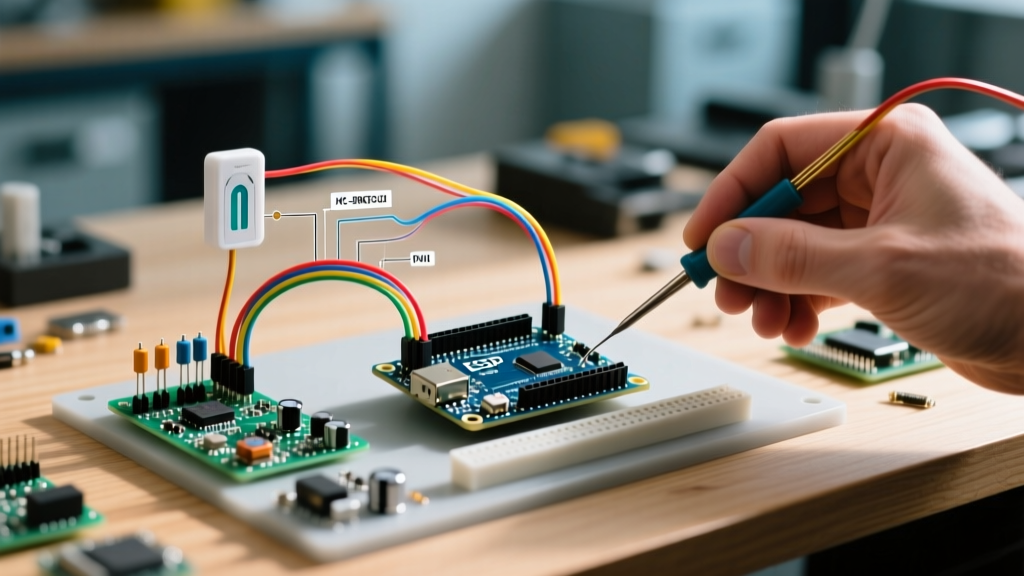

The Hardware Reality: Choosing the Right PIR Module
When makers and engineers search for a 'sensor pir arduino' solution, they are usually met with elementary tutorials demonstrating a simple digitalRead() inside the loop() function. While this works for a 5-minute classroom demonstration, it fails catastrophically in real-world deployments. Passive Infrared (PIR) sensors are notoriously noisy, susceptible to electromagnetic interference (EMI), and governed by complex internal timing circuits that require sophisticated software state machines to manage properly.
Before writing a single line of driver code, you must understand the hardware you are interfacing with. The market is dominated by three distinct modules, each requiring a different software approach.
| Module | Core IC | Voltage | Avg Price (2026) | Software Driver Requirement |
|---|---|---|---|---|
| HC-SR501 | BISS0001 | 5V - 20V | $1.50 | Interrupt + Lockout Timer (Adjustable Pots) |
| SR602 | BISS0001 Variant | 3.3V - 5V | $1.20 | Edge Detection + Fixed 2.5s Cooldown |
| Panasonic EKMC | Custom ASIC | 3V - 6V | $8.50 | Simple Polling (Ultra-stable, low EMI) |
The 'Library' Misconception: State Machines over I2C Drivers
Unlike an I2C temperature sensor or an SPI display, a PIR sensor does not have a register map, a baud rate, or a complex communication protocol. It outputs a simple digital HIGH or LOW. Therefore, searching for a dedicated 'PIR Library' is fundamentally misguided. What you actually need is a State Machine and Debounce Library.
The most robust approach to handling a sensor PIR Arduino integration is to treat the PIR module exactly like a highly noisy, slow-acting mechanical button. By leveraging button-debouncing libraries and non-blocking task schedulers, you can eliminate 99% of false triggers.
Recommended Library Stack
- Bounce2: Originally designed for mechanical switches, this library is perfect for filtering out the microsecond-scale EMI spikes that plague the HC-SR501 when nearby relays switch on or off.
- TaskScheduler: Essential for managing the sensor's mandatory 'lockout' and 'warm-up' periods without using the blocking
delay()function.
Pattern 1: Software Debouncing with Bounce2
If you are using the SR602 or a Panasonic EKMC module in an environment with heavy electrical noise (like a garage door opener or HVAC control board), the Bounce2 library is your best defense. By setting a debounce interval of 50ms to 100ms, you instruct the Arduino to ignore any transient HIGH pulses that do not persist, effectively filtering out RF rectification noise.
#include <Bounce2.h>

Bounce pirDebouncer = Bounce();
const int PIR_PIN = 2;

void setup() {
  pinMode(PIR_PIN, INPUT);
  pirDebouncer.attach(PIR_PIN, INPUT);
  pirDebouncer.interval(100); // 100ms debounce for EMI filtering
}

void loop() {
  pirDebouncer.update();
  if (pirDebouncer.rose()) {
    // Valid motion detected, execute non-blocking action
  }
}
Pattern 2: The Interrupt-Driven PIR Driver
For battery-powered nodes using an ESP32 or an ATmega328P in sleep mode, polling is not an option. You must use hardware interrupts. However, a naive attachInterrupt() implementation will crash your system or drain your battery due to the BISS0001 chip's internal retriggering behavior.
According to the official Arduino attachInterrupt reference, Interrupt Service Routines (ISRs) must be as short as possible. You should never use delay(), Serial.print(), or complex math inside an ISR. Instead, use the ISR solely to set a volatile flag and record a timestamp.
volatile bool motionFlag = false;
volatile unsigned long lastMotionTime = 0;
const unsigned long LOCKOUT_PERIOD = 3000; // 3 second software lockout

void IRAM_ATTR pirISR() {
  unsigned long currentTime = millis();
  // Prevent interrupt flooding during the BISS0001 retrigger window
  if (currentTime - lastMotionTime > LOCKOUT_PERIOD) {
    motionFlag = true;
    lastMotionTime = currentTime;
  }
}

void setup() {
  pinMode(2, INPUT_PULLDOWN);
  attachInterrupt(digitalPinToInterrupt(2), pirISR, RISING);
}
Advanced E-E-A-T: BISS0001 Internal Timing & Warm-Up
To truly master the sensor PIR Arduino ecosystem, you must understand the analog timing network governing the ubiquitous BISS0001 chip found in 90% of hobbyist modules. As detailed in the Adafruit PIR Sensor Guide, the chip relies on external resistors and capacitors to dictate its behavior.
The Warm-Up Period (Ti)
When power is first applied, the PIR sensor must calibrate its ambient infrared baseline. This is governed by the formula: Ti ≈ 24 * R9 * C10. On a standard HC-SR501, R9 is 1MΩ and C10 is 10µF, resulting in a ~24-second initialization period. Critical Rule: Your Arduino driver must implement a software blind-spot for the first 30 seconds after boot. If you fail to do this, your system will register a false 'motion detected' event every time it powers on or wakes from deep sleep.
The Lockout Time (Tx)
After a trigger, the chip disables further detection to allow the pyroelectric element to reset. Tx ≈ 2.5 * R10 * C6. With the stock 1MΩ and 10nF components, this is ~2.5 seconds. If you are building a high-speed people counter, you can physically replace the SMD C6 capacitor with a 1nF capacitor to reduce the hardware lockout to ~0.25 seconds, shifting the burden of timing management entirely to your Arduino software.
Real-World Edge Cases: EMI and Power Supply Ripple
The most common point of failure in advanced PIR deployments is Electromagnetic Interference (EMI), particularly when pairing a sensor PIR Arduino setup with Wi-Fi or Bluetooth modules like the ESP32-C3 or ESP8266.
Pro-Tip: The 2.4GHz Rectification Problem
The high-gain operational amplifiers inside the BISS0001 chip can inadvertently act as crystal radios. When an ESP32 transmits a Wi-Fi packet at 2.4GHz, the RF energy can be rectified by the PIR's internal op-amps, causing the output pin to spike HIGH. This results in 'ghost' motion triggers every time the microcontroller connects to the network.
Hardware Mitigations for the Driver Engineer
- Decoupling: Place a 100µF electrolytic capacitor and a 100nF ceramic capacitor directly across the VCC and GND pins of the PIR module, not just on the Arduino breadboard.
- Ferrite Beads: If your PIR is mounted remotely via a JST cable, place a 600Ω @ 100MHz ferrite bead on the VCC line to choke high-frequency RF noise traveling down the wire.
- Twisted Pair: Run the Signal, VCC, and GND wires as a twisted bundle to minimize the loop area acting as an antenna.
Integrating with ESP32 Deep Sleep
For off-grid, solar-powered security nodes, the PIR sensor must wake the microcontroller from deep sleep. The Espressif Sleep Modes API allows you to use the EXT0 or EXT1 wake-up sources. However, because the HC-SR501 draws roughly 50µA to 65µA of quiescent current, it will slowly drain a lithium-ion battery over weeks. For ultra-low-power applications, bypass the HC-SR501 entirely and use the Panasonic EKMC series, which draws a mere 170µA but offers vastly superior immunity to RF interference, making your software driver significantly simpler to write and maintain.
Summary Decision Matrix
Building a reliable sensor PIR Arduino driver is less about finding a magic library and more about implementing robust state management and hardware-aware timing. Use Bounce2 for noisy industrial environments, leverage attachInterrupt with strict lockout timers for battery-powered sleep nodes, and always respect the 30-second BISS0001 warm-up calibration window in your initialization code.