
The I2C Bottleneck in Multi-Peripheral Robotics
When scaling a robotics, animatronics, or automated camera rig beyond three or four actuators, the native PWM pins on standard microcontrollers like the ATmega328P or ESP32 quickly become a severe bottleneck. Furthermore, in a complex multi-peripheral setup—where you are simultaneously polling BNO055 IMUs, reading VL53L1X LiDAR sensors, and driving OLED displays—relying on software-based PWM generation causes interrupt conflicts and severe signal jitter. The definitive solution is offloading PWM generation to a dedicated I2C peripheral.
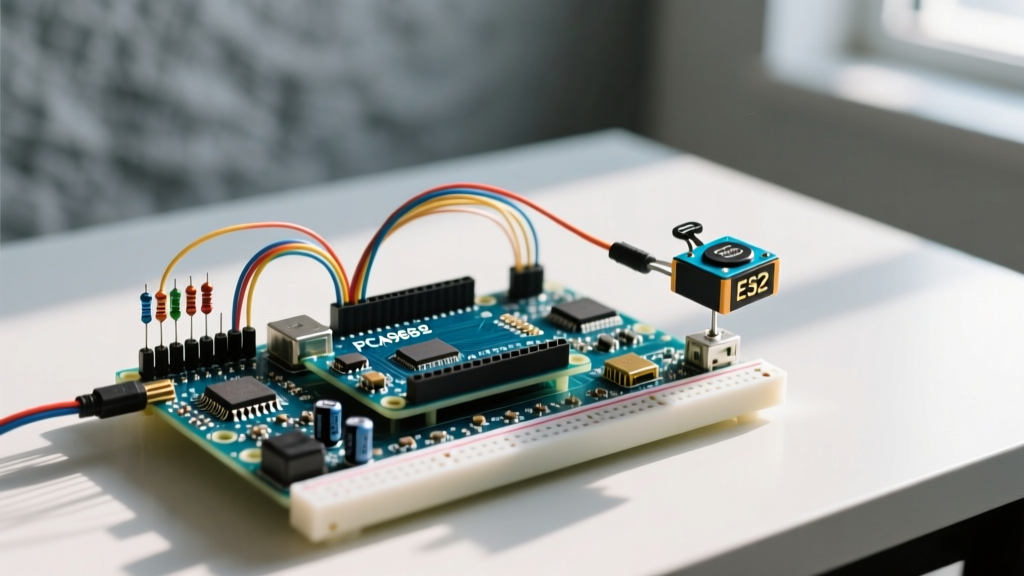
In this guide, we will deep-dive into integrating a PCA9685-based arduino servo driver into a crowded I2C bus. We will cover hardware selection, power architecture for high-stall-current servos, I2C bus capacitance management, and the precise software math required for jitter-free actuation.
Selecting Your Arduino Servo Driver: Hardware Comparison
The NXP PCA9685 is the undisputed industry standard for I2C PWM generation. It features 16 channels, a 12-bit resolution (4096 steps), and a programmable frequency range from 24Hz to 1526Hz. However, the physical breakout board you choose drastically impacts your multi-peripheral setup's reliability. As of 2026, the market is split between premium shield-style boards and bare-bones clones.
| Module Variant | Avg. Price (2026) | Logic Level | Onboard Decoupling | Best Use Case |
|---|---|---|---|---|
| Adafruit 2.3 (PID 815) | $14.95 | 5V Tolerant w/ Logic IC | Excellent (Tantalum) | Prototyping, mixed 3.3V/5V I2C buses |
| Generic PCA9685 Clone | $3.50 - $4.80 | Direct NXP Pinout | Poor (Often missing caps) | Budget rigs, custom PCB integration |
| SparkFun PWM Shield | $19.99 | 5V Arduino Shield | Good (Electrolytic) | Direct Arduino Uno/Mega stacking |
Expert Note: If you are using a 3.3V microcontroller (like an ESP32 or Raspberry Pi Pico) alongside 5V sensors on the same I2C bus, the Adafruit board includes a dedicated level-shifting IC that prevents 5V logic from back-feeding and destroying your MCU's GPIO pins.
Engineering the Power Architecture (Avoiding the 5V Melt)
The most catastrophic failure mode in multi-servo setups is attempting to power the servos through the Arduino's onboard 5V linear regulator. Standard MG996R metal-gear servos can draw upwards of 2.5A each during a stall condition. If you command six servos to move simultaneously, you risk a 15A current spike.
CRITICAL WARNING: The Arduino Uno R3's onboard NCP1117 voltage regulator will thermally throttle and shut down at around 500mA to 800mA. Pushing servo power through the MCU's 5V pin will permanently damage the board's copper traces and silicon.
The BEC Solution
For any rig utilizing more than two standard servos, you must use a dedicated Switching Battery Eliminator Circuit (BEC). A 5V 10A UBEC (Universal BEC) from manufacturers like Hobbywing or Castle Creations costs between $12 and $25 and provides clean, high-current switching power.
- Wiring the V+ Terminal: Connect the BEC's 5V output directly to the green V+ terminal block on the PCA9685 driver.
- Shared Ground: The BEC ground, the PCA9685 ground, and the Arduino ground must be tied together. Without a common ground reference, the I2C logic signals will float, resulting in erratic bus behavior.
- Bulk Capacitance: Solder a 1000µF to 2200µF low-ESR electrolytic capacitor directly across the V+ and GND pins on the servo terminal block. This acts as a local energy reservoir to absorb microsecond current spikes during servo startup, preventing brownouts on your I2C sensors.
I2C Bus Topology and Address Mapping
When integrating an arduino servo driver into a bus that already hosts displays and environmental sensors, I2C address collisions and bus capacitance become primary concerns.
Resolving Address Conflicts
The default I2C address for the PCA9685 is 0x40. If you are chaining multiple drivers or if another peripheral (like certain OLED displays) hogs this address, you must shift it using the A0-A5 solder pads on the board.
- A0 Closed: Address shifts to
0x41 - A1 Closed: Address shifts to
0x42 - A0 + A1 Closed: Address shifts to
0x43
According to the NXP PCA9685 Datasheet, you can cascade up to 62 devices on a single bus by utilizing the ALLCALL address feature, though physical bus limits will restrict this in practice.
Managing Bus Capacitance and Pull-Up Resistors
The I2C specification mandates a maximum bus capacitance of 400pF. Every peripheral, breakout board, and inch of wire adds parasitic capacitance. A generic PCA9685 clone adds roughly 15pF, while long ribbon cables can add 2pF per inch. If your bus capacitance exceeds 400pF, the signal edges will round off, causing the Arduino Wire Library to throw timeout errors.
The Fix: If you are running a crowded bus with a PCA9685, an OLED, and an IMU, drop the standard 4.7kΩ pull-up resistors down to 2.2kΩ. This provides a stronger pull-up current, sharpening the signal rise times and allowing you to safely use Wire.setClock(400000); for 400kHz Fast Mode operation.
Software: Calculating PWM Ticks for Precision Actuation
Unlike the standard Arduino Servo.h library which abstracts pulse widths into degrees, the PCA9685 operates on raw 12-bit tick values. To achieve smooth, multi-peripheral synchronized movement, you must understand the underlying math.
Standard hobby servos expect a 50Hz signal (a 20ms period). The PCA9685 divides this period into 4096 discrete steps.
- Time per step: 20ms / 4096 = 4.88 microseconds per step
- 1ms pulse (0 degrees): 1000µs / 4.88µs = 205 ticks
- 1.5ms pulse (90 degrees): 1500µs / 4.88µs = 307 ticks
- 2ms pulse (180 degrees): 2000µs / 4.88µs = 410 ticks
Implementation Snippet
When initializing the driver in your setup loop, ensure you explicitly set the PWM frequency. While the Adafruit PWM Servo Driver Guide provides excellent wrapper libraries, calling the raw register writes reduces I2C bus overhead in high-priority interrupt routines.
pwm.setPWMFreq(50); // Set to exactly 50Hz for standard servos
Troubleshooting Jitter and Edge Cases
Even with perfect wiring, multi-peripheral setups can introduce noise that manifests as servo jitter. Here is how to diagnose the specific failure modes:
1. Micro-Jitter at Rest
Symptom: The servo hums and twitches slightly when it should be holding still.
Cause: I2C bus noise or a floating PWM signal.
Solution: Ensure your I2C cables are routed away from the high-current BEC power lines. If using ribbon cables, alternate ground and signal wires (e.g., GND, SDA, GND, SCL, GND) to provide electrostatic shielding.
2. Brownout Resets During Sweeps
Symptom: The Arduino reboots or the I2C OLED display goes blank when multiple servos move simultaneously.
Cause: Voltage sag on the 5V rail pulling the I2C logic low.
Solution: Your BEC is undersized, or your bulk capacitor is too small. Upgrade to a 10A+ switching regulator and add a 0.1µF ceramic decoupling capacitor directly across the VCC and GND pins on the PCA9685 IC itself.
3. I2C Bus Lockups
Symptom: The Wire.endTransmission() function hangs indefinitely after a power spike.
Cause: A voltage spike caused a peripheral to pull the SDA line low, deadlocking the I2C state machine.
Solution: Implement a software I2C bus watchdog. If a transmission times out, toggle the SCL pin manually via GPIO bit-banging 9 times to release the stuck peripheral, then reinitialize the Wire library.
Final Integration Checklist
Before powering on your multi-peripheral rig, verify the following:
- [ ] Servo power is supplied by a dedicated 5V BEC, NOT the Arduino 5V pin.
- [ ] A minimum 1000µF capacitor is installed on the PCA9685 terminal block.
- [ ] MCU Ground, BEC Ground, and PCA9685 Ground are tied at a single star point.
- [ ] I2C pull-up resistors are sized correctly (2.2kΩ for crowded buses).
- [ ] Address jumpers are soldered cleanly to prevent floating logic states.
By treating your arduino servo driver not just as an accessory, but as a high-current node that interacts with your sensitive I2C sensor network, you will achieve the rock-solid reliability required for professional-grade robotics and automation.