
Beyond I2C Modules: Why Choose Analog Piezoresistive Sensors?
While digital I2C sensors like the BMP280 dominate hobbyist weather stations, industrial and automotive DIY projects often demand the ruggedness, media isolation, and higher pressure ranges of analog piezoresistive sensors. Connecting an analog pressure sensor to Arduino microcontrollers introduces unique challenges regarding signal conditioning, ratiometric mathematics, and ADC resolution. This guide focuses on the NXP MPX4115A (15–115 kPa absolute pressure sensor), a staple in 2026 for custom barometric, altitude, and vacuum manifold applications.
Hardware BOM & Signal Conditioning
Raw analog pressure sensors are highly susceptible to electromagnetic interference (EMI) and power supply ripple. Do not wire the sensor directly to the Arduino without passive filtering.
| Component | Specification | Estimated Cost (2026) | Purpose |
|---|---|---|---|
| NXP MPX4115A | Absolute, 15-115 kPa, DIP-6 | $7.50 - $8.50 | Primary piezoresistive transducer |
| Arduino Uno R4 Minima | 12-bit ADC, 5V logic | $20.00 | Microcontroller (12-bit ADC recommended) |
| Ceramic Capacitor (C1) | 100nF (0.1µF) MLCC | $0.05 | High-frequency decoupling on VCC |
| Tantalum Capacitor (C2) | 10µF, 16V | $0.15 | Bulk energy storage, low-freq ripple filter |
| Resistor (R1) & Cap (C3) | 10kΩ & 100nF | $0.10 | Hardware Low-Pass Filter (LPF) on Vout |
Wiring & Hardware Low-Pass Filter
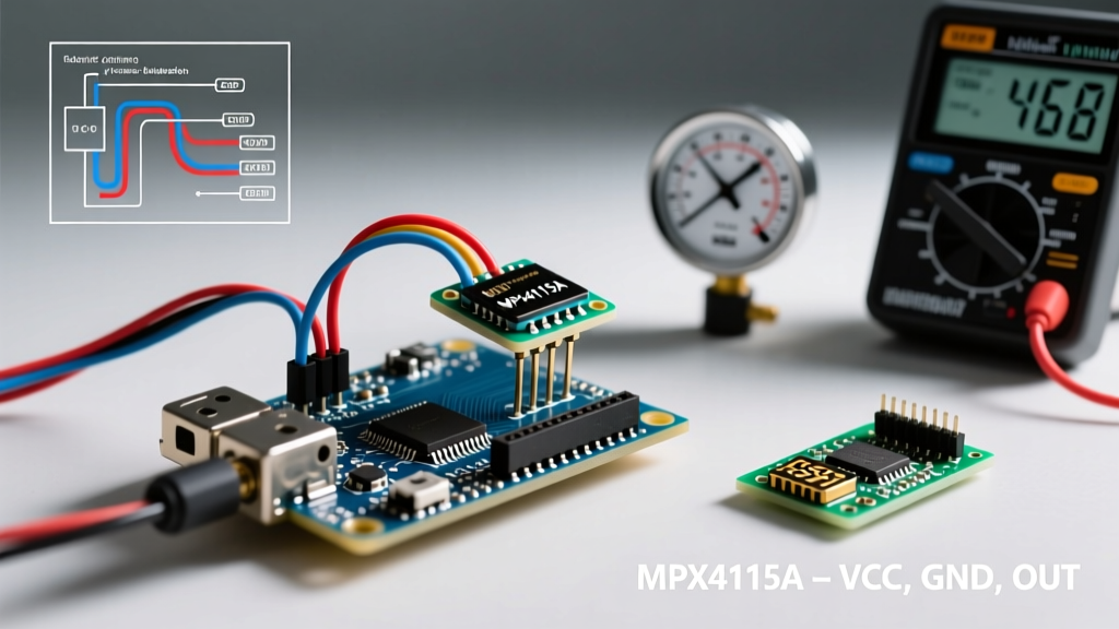
The MPX4115A outputs a varying voltage between 0.2V (at 15 kPa) and 4.7V (at 115 kPa) when supplied with 5V. To interface this pressure sensor to Arduino analog pins safely:
- Power Decoupling: Place the 100nF ceramic and 10µF tantalum capacitors in parallel across the sensor's VCC (Pin 1) and GND (Pin 2). Keep leads under 5mm to minimize parasitic inductance.
- Signal Filtering: Connect a 10kΩ resistor in series with the Vout (Pin 4). At the Arduino A0 pin side of the resistor, connect the 100nF capacitor to GND. This creates an RC low-pass filter with a cutoff frequency of roughly 159 Hz ($f_c = \frac{1}{2\pi RC}$), effectively eliminating high-frequency switching noise from nearby DC-DC converters.
- Grounding: Route the sensor GND directly to the Arduino's analog ground pin, avoiding shared ground paths with high-current peripherals like motors or relays.
The Ratiometric Advantage: Math & ADC References
The most common mistake makers make when wiring an analog pressure sensor to Arduino is ignoring ratiometric behavior. The MPX4115A output is proportional to its supply voltage. If your Arduino's 5V rail sags to 4.8V under load, the sensor's output voltage drops proportionally, even if the physical pressure remains constant.
Manufacturer Transfer Function:
Vout = VCC × (0.009 × PkPa - 0.095)
To achieve high accuracy, you must use the Arduino's default analog reference (which ties the ADC reference to VCC). When both the sensor excitation and the ADC reference share the same VCC rail, the VCC variable cancels out in the digital domain.
Calculating Pressure from ADC Raw Values
Instead of converting the ADC reading back to volts, use the ratio of the ADC reading to the maximum ADC value. For a 12-bit ADC (Arduino Uno R4), the max value is 4095.
Ratio = ADC_Raw / 4095
Rearranging the transfer function to solve for Pressure (P):
P_kPa = (Ratio + 0.095) / 0.009
This ratiometric approach completely eliminates errors caused by USB voltage drops or linear regulator drift, a critical technique validated by Texas Instruments' ADC design guidelines for ratiometric sensor chains.
Step-by-Step Two-Point Calibration Protocol
Factory calibration guarantees the MPX4115A is within ±1.5% of Full Scale Span (FSS). However, for precision applications, a two-point field calibration is mandatory to account for hardware tolerances and the RC filter's slight voltage drop.
Point 1: Atmospheric Baseline (Zero-Gauge Equivalent)
- Leave the sensor port open to ambient room air.
- Look up your exact local barometric pressure via a live METAR aviation weather report or a calibrated local weather station. Do not rely on generic internet weather apps, which often report sea-level adjusted pressure rather than absolute station pressure.
- Record the stable ADC average (e.g., 1000 samples). Let's assume local absolute pressure is 101.3 kPa and your ADC reads 3350.
Point 2: Applied Known Pressure
- Connect a calibrated manual hand-pump (like a digital bicycle pump or a laboratory deadweight tester) to the sensor port via silicone tubing.
- Apply a known pressure near the upper end of your expected operating range (e.g., 110.0 kPa).
- Record the new stable ADC average (e.g., 3640).
- Calculate your custom slope and intercept using linear regression ($y = mx + b$) in your Arduino code, replacing the factory 0.009 and 0.095 constants.
Resolution Matrix: 10-bit vs 12-bit vs 16-bit ADC
When connecting a pressure sensor to Arduino, your choice of microcontroller dictates your baseline resolution. The MPX4115A has a sensitivity of roughly 45mV/kPa at 5V.
| ADC Resolution | Typical MCU (2026) | Voltage per Step (at 5V) | Pressure Resolution | Best Use Case |
|---|---|---|---|---|
| 10-bit (1024) | Arduino Uno R3 / Nano | 4.88 mV | ~0.108 kPa / step | Basic weather trends, leak detection |
| 12-bit (4096) | Arduino Uno R4 Minima | 1.22 mV | ~0.027 kPa / step | Altitude tracking, precision pneumatics |
| 16-bit (65536) | ADS1115 (External I2C) | 0.15 mV (at 6.144V FSR) | ~0.003 kPa / step | Laboratory metrology, micro-leak testing |
Note: Upgrading to the Arduino Uno R4's 12-bit ADC provides a 4x resolution improvement over legacy 8-bit AVRs without the noise floor complications of external 16-bit ADCs on unshielded breadboards.
Troubleshooting & Edge Cases
1. Thermal Drift and Hysteresis
Piezoresistive silicon elements exhibit thermal drift. The MPX4115A features internal laser-trimmed temperature compensation, but rapid ambient temperature swings (e.g., moving from a 20°C lab to a -5°C garage) will cause temporary reading spikes. Solution: Implement a software moving-average filter (window size of 50) and allow the sensor 15 minutes to reach thermal equilibrium before executing your calibration routine.
2. The 'Sticky' Reading (Hysteresis)
If your sensor reads higher after being subjected to maximum pressure, you are experiencing hysteresis. The MPX4115A has a typical hysteresis of ±0.5% VFSS. To mitigate this in software, always approach your calibration points from the same direction (e.g., always pump up to the target pressure, never bleed down to it).
3. 50Hz/60Hz Mains Hum
If your readings fluctuate rhythmically, your hardware LPF is insufficient, or your ground plane is contaminated by AC mains coupling. Ensure your sensor wiring is twisted-pair and kept at least 5cm away from any AC-to-DC power bricks. For software mitigation, sample the ADC at exactly 600Hz (a multiple of both 50 and 60) and average over 10ms or 20ms windows to mathematically cancel out the AC ripple.
Summary
Successfully integrating an analog pressure sensor to Arduino requires moving beyond simple `analogRead()` commands. By implementing proper hardware RC filtering, leveraging ratiometric mathematics to ignore VCC sag, and executing a rigorous two-point calibration against live METAR data, you can extract laboratory-grade accuracy from a sub-$10 NXP transducer. For further component selection, review the NXP Pressure Sensors portfolio to match the exact kPa range and media compatibility required for your specific 2026 project.