
Architecting a Multi-Peripheral Metal Sensor Arduino Sorting System
Integrating a metal sensor Arduino setup into a multi-peripheral environment is a cornerstone of modern DIY automation, particularly for automated sorting rigs, robotic end-effectors, and quality control conveyors. While triggering a single LED with a proximity probe is a common beginner project, scaling this to a multi-peripheral system—incorporating an I2C OLED display for real-time telemetry, a high-torque servo for mechanical diversion, and a relay module for secondary actuation—introduces complex electrical challenges. In 2026, with the widespread availability of cheap industrial inductive sensors and high-refresh-rate microcontroller displays, the primary point of failure in these builds is no longer software logic, but rather mixed-voltage signal interference and power rail brownouts.
This guide details the exact hardware selection, galvanic isolation techniques, and state-machine programming required to build a robust, industrial-grade metal detection and sorting rig using an ATmega328P-based microcontroller.
Bill of Materials and Component Specifications
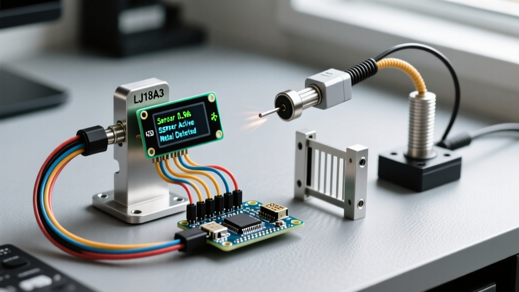
To ensure reliable detection of ferrous and non-ferrous metals (depending on the target material), we utilize an industrial-grade inductive proximity sensor rather than a hobbyist coil-based detector module. Below is the curated BOM for a complete multi-peripheral sorting node.
| Component | Model / Specification | Function | Est. Cost (2026) |
|---|---|---|---|
| Inductive Sensor | LJ18A3-8-Z/BX (NPN, NO, 18mm) | Detects metal targets up to 8mm away | $11.50 |
| Optocoupler | PC817 or 4N35 | Galvanic isolation for 12V-to-5V logic | $0.15 |
| Microcontroller | Arduino Nano (ATmega328P) | Central processing and peripheral routing | $6.00 |
| Display | SSD1306 128x64 I2C OLED (SH1106G) | Visual telemetry and metal count stats | $7.50 |
| Actuator | MG996R Metal Gear Servo | Physical sorting gate diversion | $7.80 |
| Power Supply | LM2596 Buck Converter (5.1V out) | Dedicated high-current rail for servo | $2.50 |
The NPN Voltage Trap: Why Direct Wiring Fries Microcontrollers
The most critical edge case when wiring a metal sensor Arduino project involves the output logic of industrial inductive sensors. The LJ18A3-8-Z/BX is an NPN Normally Open (NO) sensor. It requires an operating voltage between 6V and 36V (typically run at 12V for optimal range stability).
When metal enters the 8mm detection zone, the internal NPN transistor activates, sinking the signal line to ground (0V). When no metal is present, the signal line floats. To read this, a pull-up resistor is required. If you wire a 10kΩ pull-up resistor to the sensor's 12V supply line to stabilize the floating state, the signal wire will carry 12V when idle. Routing a 12V signal directly into a 5V-tolerant GPIO pin on the Arduino will instantly destroy the microcontroller's input register.
⚠️ Critical Warning: Never use a simple resistive voltage divider for high-speed inductive sensor signals. Voltage dividers introduce impedance that, combined with the parasitic capacitance of long sensor cables, creates an RC low-pass filter. This rounds off the square-wave signal edges, leading to missed detections on fast-moving conveyor belts.
Implementing Galvanic Isolation via Optocoupler
To safely interface the 12V industrial sensor with the 5V Arduino logic while preserving sharp signal edges, we use a PC817 optocoupler. This provides 100% electrical isolation, protecting the microcontroller from voltage spikes and ground loops inherent in industrial environments. As detailed in the Electronics Tutorials guide on optocouplers, the internal LED and phototransistor allow signal transfer via light, completely breaking the electrical circuit.
Step-by-Step Isolation Wiring
- Sensor Power: Connect the LJ18A3 Brown wire to 12V+ and the Blue wire to System GND.
- Optocoupler Input (Anode): Connect the 12V+ line through a 1.5kΩ current-limiting resistor to Pin 1 (Anode) of the PC817.
- Optocoupler Input (Cathode): Connect the LJ18A3 Black (Signal) wire to Pin 2 (Cathode) of the PC817. When metal is detected, the sensor sinks this line to GND, completing the circuit and illuminating the internal LED.
- Optocoupler Output (Emitter): Connect Pin 4 (Emitter) to the Arduino GND.
- Optocoupler Output (Collector): Connect Pin 3 (Collector) to Arduino Digital Pin 2. Enable the internal pull-up resistor in software (
INPUT_PULLUP). The pin will read HIGH when idle, and cleanly drop to LOW when metal is detected.
Multi-Peripheral Power Rail Management
Integrating an MG996R servo and an SSD1306 OLED on the same 5V rail as the Arduino is a recipe for I2C bus lockups. The MG996R can draw up to 2.5A during stall conditions. If powered via the Arduino's onboard linear regulator, the resulting voltage sag will cause the ATmega328P to brownout and reset, while the sudden current spike will introduce massive electromagnetic interference (EMI) onto the I2C lines, freezing the OLED display.
The Solution: Use an LM2596 buck converter to step down your main 12V supply to a dedicated 5.1V rail. Wire the servo's power and ground directly to this buck converter. Crucially, you must tie the grounds together (Arduino GND and Buck Converter GND) using at least 18 AWG wire to establish a common ground reference for the PWM control signal. Place a 100µF electrolytic capacitor and a 0.1µF ceramic decoupling capacitor directly across the servo's power terminals at the connector to absorb inductive kickback and high-frequency noise.
State Machine Logic for Multi-Peripheral Coordination
When coordinating a metal sensor, a servo gate, and an I2C display, using blocking delay() functions is fatal. If the Arduino pauses to wait for a servo to sweep, it will completely miss a fast-moving metal target on the sensor line. Instead, we implement a non-blocking, event-driven state machine.
When configuring the actuator, referencing the official Arduino Servo library documentation is essential for understanding PWM timing constraints. Below is the architectural flow for the loop() function:
- STATE_IDLE: Continuously poll Digital Pin 2. Update the OLED display every 500ms via
millis()to show the total metal count. If Pin 2 goes LOW, transition to STATE_DETECTED. - STATE_DETECTED: Log the exact timestamp using
micros()to implement a 20ms software debounce filter (ignoring EMI spikes). Increment the metal counter. Command the servo to 90° (divert gate). Transition to STATE_ACTUATING. - STATE_ACTUATING: Monitor the servo position. Once the physical gate is fully open and a predefined 800ms mechanical clearance window has passed, transition to STATE_RESETTING.
- STATE_RESETTING: Command the servo back to 0° (default path). Once the reset is complete, transition back to STATE_IDLE.
For the display interface, the Adafruit OLED wiring guide provides the foundational I2C setup, but remember to initialize the SH1106G driver if your 2026-purchased display uses the newer, higher-contrast controller chips rather than the legacy SSD1306.
Real-World Failure Modes and EMI Troubleshooting
Even with perfect wiring, a multi-peripheral metal sensor Arduino rig can suffer from 'ghost detections'—where the sensor triggers without any metal present. In 90% of cases, this is caused by Electromagnetic Interference (EMI) generated by the servo motor's internal DC brushes.
Mitigation Strategies
- Twisted Pair Cabling: Always use twisted pair cable for the sensor's signal and ground lines. This ensures that any induced magnetic noise affects both wires equally, canceling out the interference (common-mode rejection).
- Ferrite Beads: Snap a ferrite bead onto the sensor cable within 2 inches of the optocoupler input. This chokes high-frequency RF noise generated by the servo.
- Software Debouncing: Inductive sensors can experience micro-oscillations at the exact edge of their detection boundary. Implement a strict 20ms to 50ms digital debounce in your STATE_DETECTED logic to ensure the signal is stable before committing to a mechanical sort.
- I2C Pull-ups: If the OLED display flickers or drops out during servo actuation, the I2C bus is suffering from noise. Add external 4.7kΩ pull-up resistors to the SDA and SCL lines, tied to the Arduino's clean 5V rail (not the noisy servo buck converter rail).
Conclusion
Building a reliable metal detection system requires looking past the basic sensor datasheet and addressing the realities of mixed-signal electronics. By isolating your 12V industrial inductive sensor with a PC817 optocoupler, segregating your high-current servo power via a dedicated buck converter, and utilizing a non-blocking state machine, your metal sensor Arduino setup will achieve industrial-level reliability. Whether you are sorting scrap, automating a packaging line, or building a complex robotics peripheral, mastering these multi-peripheral integration techniques is what separates fragile prototypes from robust, deployment-ready hardware.