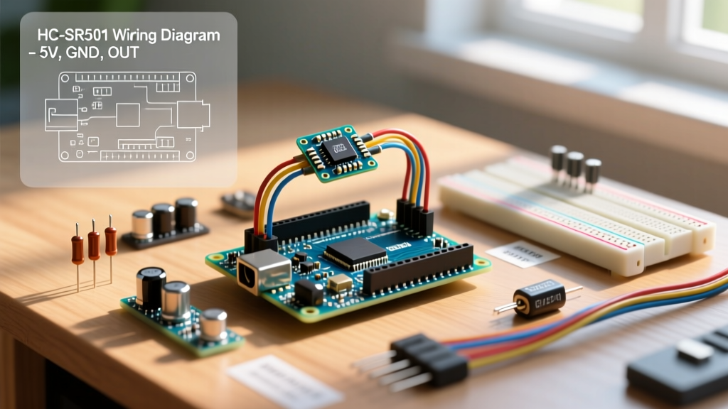

Mastering the Motion Sensor Arduino Integration
Integrating a motion sensor Arduino setup remains a cornerstone of DIY security, automated lighting, and IoT edge nodes. While the fundamental physics of passive infrared (PIR) detection haven't changed, the way we interface these sensors with modern 3.3V microcontrollers in 2026 requires a much more rigorous approach than the basic 5V tutorials of the past. Whether you are building a battery-powered wildlife camera trigger or a smart-home occupancy node, understanding the silicon, the optics, and the code architecture is critical for eliminating false triggers and phantom wakes.
In this comprehensive sensor integration tutorial, we will dissect the ubiquitous HC-SR501 PIR module, explore miniature and microwave alternatives, and provide production-ready C++ code utilizing hardware interrupts and non-blocking debounce logic.
Sensor Selection: PIR vs. Microwave vs. Miniature
Before wiring anything, you must select the right sensor topology for your environment. The standard HC-SR501 is a staple, but modern supply chains offer diverse alternatives. According to the physics of passive infrared sensing, PIR sensors do not detect heat directly; they detect changes in infrared radiation across a segmented pyroelectric crystal.
| Sensor Module | Technology | Operating Voltage | Detection Range | Avg. 2026 Price | Best Use Case |
|---|---|---|---|---|---|
| HC-SR501 | Standard PIR (BISS0001) | 4.5V - 20V | Up to 7m (120°) | $1.20 - $1.80 | Room occupancy, alarm systems |
| AM312 | Miniature PIR | 2.7V - 12V | Up to 3m (100°) | $1.50 - $2.20 | Wearables, compact battery nodes |
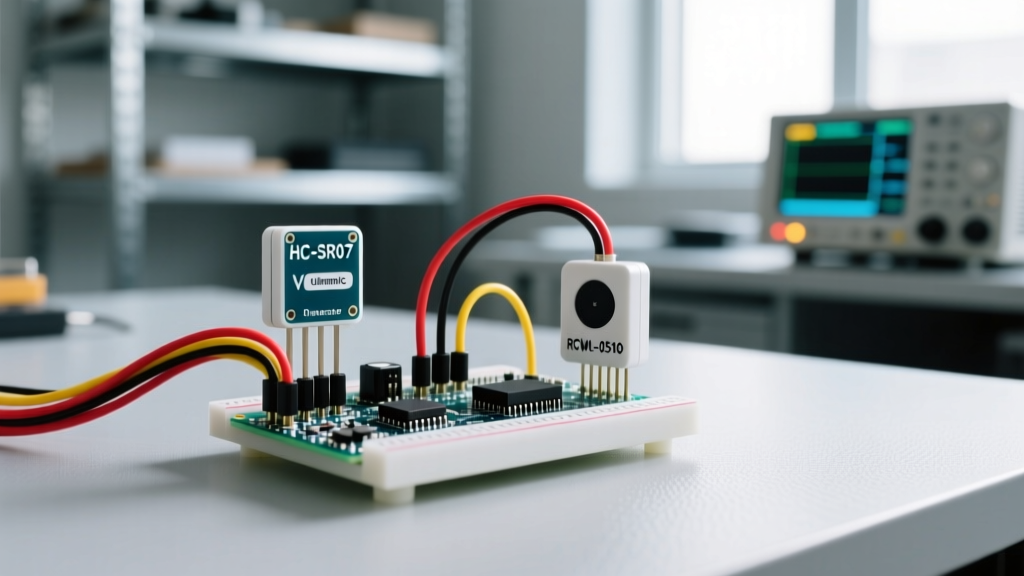
| RCWL-0516 | Microwave Radar | 4V - 28V | Up to 9m (Through-wall) | $2.00 - $2.80 | Hidden sensors, outdoor enclosures |
The Fresnel Lens Factor
The white plastic dome on the HC-SR501 is a Fresnel lens made of high-density polyethylene. It focuses ambient IR radiation onto the tiny pyroelectric sensor window. If you are designing a custom 3D-printed enclosure, do not use standard PLA or PETG to cover the sensor; these materials block IR wavelengths. You must either leave an aperture for the dome or use specialized IR-transmissive acrylic.
Wiring and the 3.3V Logic Level Trap
The most common failure mode in modern motion sensor Arduino projects occurs when makers connect a 5V HC-SR501 output directly to a 3.3V GPIO pin on an ESP32, Arduino Nano 33 IoT, or Raspberry Pi Pico. The HC-SR501 output pin swings up to its VCC voltage (usually 5V). Feeding 5V into a 3.3V logic pin will eventually degrade or destroy the microcontroller's internal ESD protection diodes.
The Voltage Divider Solution
To safely interface the HC-SR501 OUT pin to a 3.3V microcontroller, use a simple resistor voltage divider:
- R1 (Series Resistor): 2.2kΩ (Connect between HC-SR501 OUT and MCU GPIO)
- R2 (Pull-down Resistor): 3.3kΩ (Connect between MCU GPIO and GND)
This specific ratio drops the 5V signal down to a safe ~3.0V, which registers as a solid HIGH on 3.3V logic families while preventing GPIO overvoltage.
⚡ Power Rail Decoupling: In dense 2026 RF environments (Wi-Fi 6E/7 routers, Bluetooth mesh), the HC-SR501's internal BISS0001 op-amp is highly susceptible to power rail noise, causing phantom triggers. Always solder a 100µF electrolytic capacitor directly across the VCC and GND pins on the PIR module's PCB to stabilize the voltage during the sensor's internal charge-pump cycles.
Production-Ready Code: Interrupts Over Polling
Beginner tutorials often use a digitalRead() inside the loop() function. This polling method is inefficient and blocks the MCU from performing other tasks or entering low-power sleep states. For a robust motion sensor Arduino integration, we use hardware interrupts. As detailed in the official Arduino interrupt documentation, this allows the MCU to react to motion in microseconds, regardless of what the main loop is executing.
Arduino C++ Implementation
// Pin Definitions (Use GPIO 2 or 3 on Uno/Nano for external interrupts)
const int PIR_INTERRUPT_PIN = 2;
const int STATUS_LED = 13;

// Volatile variables for ISR communication
volatile bool motionDetected = false;
volatile unsigned long lastTriggerTime = 0;
const unsigned long DEBOUNCE_DELAY = 250; // 250ms hardware debounce

void setup() {
  Serial.begin(115200);
  pinMode(STATUS_LED, OUTPUT);
  pinMode(PIR_INTERRUPT_PIN, INPUT);

  // Attach interrupt on RISING edge (LOW to HIGH transition)
  attachInterrupt(digitalPinToInterrupt(PIR_INTERRUPT_PIN), motionISR, RISING);

  Serial.println("Motion Sensor Node Initialized.");
  Serial.println("Calibrating sensor... (Do not move for 30s)");
  delay(30000); // HC-SR501 requires 30s boot lockout for baseline calibration
  Serial.println("Calibration complete. Active monitoring.");
}

void loop() {
  if (motionDetected) {
    motionDetected = false; // Reset flag

    digitalWrite(STATUS_LED, HIGH);
    Serial.print("[MOTION TRIGGERED] Timestamp: ");
    Serial.println(millis());

    // Execute payload (e.g., send MQTT message, trigger relay)
    executePayload();

    digitalWrite(STATUS_LED, LOW);
  }

  // Main loop is free for deep sleep or other sensor polling
  // LowPower.powerDown(SLEEP_8S, ADC_OFF, BOD_OFF);
}

// Interrupt Service Routine (ISR)
void motionISR() {
  unsigned long currentTime = millis();
  // Non-blocking debounce logic
  if (currentTime - lastTriggerTime > DEBOUNCE_DELAY) {
    motionDetected = true;
    lastTriggerTime = currentTime;
  }
}

void executePayload() {
  // Placeholder for your specific application logic
  delay(500);
}
Advanced Troubleshooting & Edge Cases
Even with perfect wiring and code, environmental factors can wreak havoc on PIR sensors. Here is how to solve the most persistent edge cases encountered in field deployments.
1. The 30-Second Boot Lockout
When power is first applied to the HC-SR501, the internal analog circuitry requires 30 to 60 seconds to sample the ambient IR environment and establish a baseline. If motion occurs during this window, the sensor may latch HIGH indefinitely or output erratic pulses. Fix: Always implement a blocking delay(30000) or a non-blocking state-machine timeout in your setup routine before enabling the interrupt.
2. HVAC and Thermal Drafts
Because PIR sensors detect changes in IR radiation, a blast of hot air from an HVAC vent moving across the sensor's field of view will register as a massive IR anomaly, triggering a false positive. Fix: Physically mask the bottom segments of the Fresnel lens with electrical tape if the sensor is mounted high on a wall, or restrict the sensor's field of view using a 3D-printed shroud tube.
3. Jumper Configuration: H vs. L Mode
The HC-SR501 features a 3-pin header for a jumper cap that dictates its timing mode:
- H Mode (Non-Retriggerable): The output goes HIGH for the duration set by the potentiometer, then goes LOW. If continuous motion occurs, it will briefly pulse LOW before going HIGH again. This can cause double-triggers in your code.
- L Mode (Retriggerable): The output stays HIGH as long as motion is continuously detected. The timer resets with every new detection. This is the recommended mode for most Arduino interrupt setups.
4. Potentiometer Tuning for Battery Nodes
The board features two trimpots: Sensitivity (Sx) and Time Delay (Tx). For battery-powered edge nodes relying on sleep modes, turn the Time Delay potentiomer all the way counter-clockwise. This reduces the hardware HIGH pulse to roughly 2.5 seconds, allowing your microcontroller to capture the interrupt, execute its payload, and return to deep sleep rapidly, saving crucial milliamp-hours.
Summary
Building a reliable motion sensor Arduino project in 2026 goes far beyond connecting three wires. By respecting the 3.3V logic thresholds, implementing hardware debounced interrupts, and mitigating environmental noise through proper decoupling and optical masking, you can transform a $1.50 component into a highly accurate, production-grade IoT trigger.