
Beyond 'Hello World': Building Real-World Sensor Dashboards
Most online tutorials for integrating a liquid crystal display Arduino setup stop at printing static text. However, deploying an LCD in a real-world environment—such as a greenhouse climate monitor, an industrial machine dashboard, or a smart thermostat—introduces complex hardware and software challenges. You must manage I2C bus capacitance, handle 3.3V versus 5V logic mismatches, and write non-blocking code to prevent screen flicker.
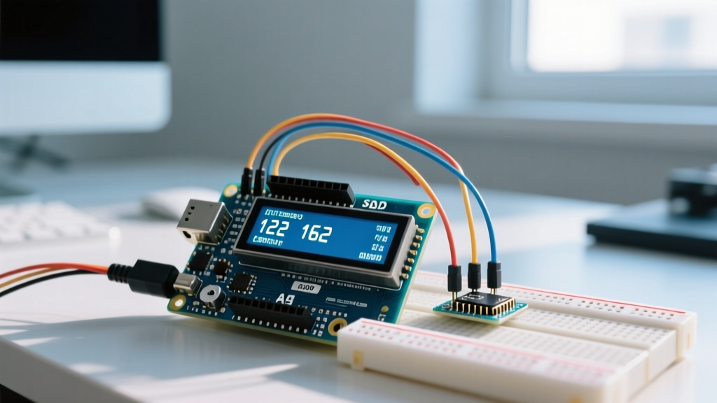
In this guide, we will architect a robust, flicker-free environmental dashboard using an Arduino Nano ESP32, a BME280 sensor, and a 20x4 I2C LCD. We will focus on the engineering edge cases that separate hobbyist prototypes from reliable 2026 deployments.
Hardware Selection: Parallel vs. I2C LCD Modules
While raw parallel HD44780 LCDs are still available, they consume six digital I/O pins and require a complex 10k potentiometer circuit for contrast control. For modern sensor dashboards, an I2C-equipped LCD module is the mandatory standard. These modules utilize an I/O expander chip mounted on a 'backpack' PCB, reducing the MCU connection to just four wires (VCC, GND, SDA, SCL).
| Feature | Raw Parallel HD44780 (16x2) | I2C LCD with PCF8574 Backpack (20x4) |
|---|---|---|
| MCU Pins Required | 6 Digital + 1 Analog (Contrast) | 2 (SDA, SCL) |
| Wiring Complexity | High (Prone to loose breadboard connections) | Low (Standardized 4-pin JST or Dupont) |
| Typical 2026 Cost | $6.00 - $9.00 | $8.00 - $14.00 |
| I2C Address Config | N/A | Jumper pads (A0, A1, A2) |
For this project, we recommend a 20x4 I2C LCD with a PCF8574T backpack (often sold under brands like DFRobot or HiLetgo). The 20x4 format provides 80 characters of real estate, allowing you to display temperature, humidity, barometric pressure, and system status simultaneously without aggressive scrolling.
The 3.3V vs. 5V Logic Trap (Critical Failure Mode)
The most common point of failure in modern liquid crystal display Arduino projects is the voltage mismatch. Standard HD44780 LCDs require a 5V VDD supply to properly drive the liquid crystals and power the backlight. However, modern high-performance boards like the Arduino Nano ESP32 or Raspberry Pi Pico operate at 3.3V logic.
Engineering Warning: The PCF8574 I/O expander on the LCD backpack requires a high-level input voltage (V_IH) of at least 0.7 × VDD. If the backpack is powered by 5V, it expects a minimum of 3.5V on the SDA and SCL lines to register a logic HIGH. A 3.3V MCU will only output 3.3V, resulting in intermittent I2C NACK errors or complete communication failure.
The Solution: Bidirectional Logic Level Shifting
Do not rely on internal MCU pull-ups to bridge this gap. You must use a dedicated BSS138-based bidirectional logic level shifter (typically costing around $3 to $5 from Adafruit or SparkFun).
- Connect the MCU's 3.3V output to the LV (Low Voltage) side of the shifter.
- Connect the LCD's 5V supply to the HV (High Voltage) side.
- Route the SDA and SCL lines through the shifter channels.
- This ensures the 3.3V logic is cleanly translated to 5V, satisfying the PCF8574 datasheet requirements outlined by NXP Semiconductors.
I2C Bus Wiring and Pull-Up Resistor Requirements
When wiring your BME280 sensor and your I2C LCD to the same bus, you are increasing the bus capacitance. The Arduino Wire library enables internal pull-up resistors by default, but these are typically 20kΩ to 50kΩ—far too weak for a multi-device bus running at 100kHz or 400kHz.
- External Pull-Ups: Solder or wire 4.7kΩ resistors between the SDA line and VCC, and the SCL line and VCC.
- Wire Length: Keep I2C traces under 30cm (12 inches). If your dashboard requires the LCD to be mounted further away, consider using an I2C bus extender like the P82B96, or switch to an SPI-based TFT display.
- Address Conflicts: The BME280 defaults to I2C address
0x76or0x77. The PCF8574T LCD backpack defaults to0x27. If your LCD uses the PCF8574AT chip, the address shifts to0x3F. Always verify addresses using an I2C scanner sketch before writing your main application logic.
Flicker-Free Code Architecture: The Delta-Update Method
In a real-world sensor dashboard, environmental data updates every 1 to 5 seconds. The naive approach is to call lcd.clear() followed by lcd.print() in the main loop. This is a catastrophic design flaw.
The lcd.clear() command sends a specific instruction to the HD44780 controller that takes approximately 1.5ms to 2.0ms to execute. During this window, the display blanks entirely. If you update the screen twice a second, the user will perceive an aggressive, eye-straining strobe effect. Furthermore, lcd.clear() is a blocking function that halts your MCU, potentially causing you to miss critical sensor interrupts.
Implementing String Caching
To achieve a premium, flicker-free UI, you must implement a 'Delta-Update' algorithm. This involves caching the previous state of the display in memory and only overwriting characters that have actually changed.
// Pseudo-code architecture for Delta-Updating
String previousLine1 = "";
String currentLine1 = "";

void updateDisplay(float temp, float humidity) {
  currentLine1 = "Temp: " + String(temp, 1) + "C";

  if (currentLine1 != previousLine1) {
    lcd.setCursor(0, 0);
    // Pad with spaces if the new string is shorter to clear old digits
    String paddedLine = currentLine1;
    while(paddedLine.length() < 20) paddedLine += " ";
    lcd.print(paddedLine);
    previousLine1 = currentLine1;
  }
}
By comparing the newly formatted string against the cached string, the lcd.print() function only fires when the physical sensor value crosses a decimal threshold. This reduces I2C bus traffic by up to 80% and completely eliminates screen flicker.
Real-World Troubleshooting Matrix
Even with perfect wiring, environmental factors and manufacturing variances can cause issues. Use this diagnostic matrix to resolve common deployment failures.
| Symptom | Root Cause | Engineering Solution |
|---|---|---|
| Top row shows solid white/black boxes; bottom row is blank. | Contrast voltage (V0) is misaligned, or initialization failed. | Adjust the blue trimpot on the I2C backpack with a small jeweler's screwdriver until characters are crisp. If that fails, check 5V VDD stability. |
| Display works on USB power, but fails when using an external 12V-to-5V buck converter. | Ground loop or insufficient current delivery from the buck converter. | LCD backlights draw 60mA-120mA. Ensure your step-down module is rated for at least 1A and shares a common ground star-point with the MCU. |
I2C Scanner finds no devices; serial monitor hangs on Wire.endTransmission(). |
Missing pull-up resistors or SDA/SCL shorted to ground. | Verify 4.7kΩ external pull-ups. Check for solder bridges on the backpack header pins. Reference the Adafruit I2C Address Guide for verification. |
| Characters randomly drop out or turn into Japanese/Custom glyphs. | Electromagnetic Interference (EMI) from nearby relays or motors. | Route I2C wires away from AC mains or inductive loads. Add a 100nF decoupling capacitor directly across the VCC and GND pins on the LCD backpack. |
Summary for Production Deployments
Integrating a liquid crystal display Arduino setup for a professional sensor dashboard requires moving beyond basic tutorials. By addressing the 3.3V/5V logic threshold with a BSS138 level shifter, reinforcing the I2C bus with 4.7kΩ pull-up resistors, and implementing a delta-update caching algorithm in your firmware, you transform a fragile hobbyist circuit into a robust, flicker-free industrial interface. Always validate your I2C addresses and power delivery before sealing your project in an enclosure, ensuring long-term reliability in the field.