
The 40kHz Landscape: Choosing Your Time-of-Flight Module
Ultrasonic time-of-flight (ToF) sensing remains a cornerstone of embedded systems, robotics, and fluid level monitoring in 2026. While LiDAR and mmWave radar have dropped in price, the classic 40kHz piezoelectric transducer still dominates low-cost, medium-range distance measurement. However, selecting the right ultrasonic sensor with Arduino code requires looking past basic tutorials. The physical acoustics, blind spots, and logic-level tolerances of different modules dictate entirely different software architectures.
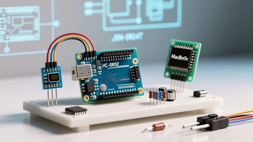
In this component comparison, we dissect the three most prevalent modules on the market: the ubiquitous HC-SR04, the waterproof JSN-SR04T (V2.0), and the premium MaxBotix MB1010. We will explore their hardware realities, failure modes, and the specific code adjustments required to make them reliable in production environments.
Component Matrix: Specifications and 2026 Pricing
| Module | Avg. Price (2026) | Effective Range | Blind Spot | Beam Angle | Logic / Interface |
|---|---|---|---|---|---|
| HC-SR04 | $1.50 - $2.20 | 2cm - 400cm | < 2cm | 15° | 5V Trigger/Echo |
| JSN-SR04T (V2.0) | $4.80 - $6.50 | 20cm - 600cm | < 20cm | 30° | 5V Trigger/Echo |
| RCWL-1601 | $2.50 - $3.50 | 2cm - 450cm | < 2cm | 15° | 3.3V/5V I2C/UART |
| MaxBotix MB1010 | $26.00 - $32.00 | 0cm - 254cm | None (0cm = Max) | 42° | 3.3V/5V Analog/PWM |
Deep Dive: Hardware Realities and Edge Cases
The JSN-SR04T Blind Spot and Versioning Trap
The JSN-SR04T is the go-to module for outdoor or high-humidity environments due to its sealed, waterproof transducer. However, this physical sealing introduces a massive acoustic trade-off: a 20cm blind spot. The piezo element is set back from the protective mesh, and the heavy dampening required to stop the waterproof membrane from 'ringing' prevents the sensor from detecting objects closer than 20cm.
Crucial Hardware Note: You must ensure you are buying the V2.0 revision of the JSN-SR04T. The older V1.0 boards lacked a proper timeout circuit. If the acoustic burst missed the target entirely, the Echo pin would latch HIGH indefinitely, freezing the Arduino's pulseIn() function and crashing your main loop. V2.0 (identifiable by the 555 timer IC on the daughterboard) fixes this, but you must still enforce a software timeout.
Acoustic Crosstalk in Multi-Sensor Arrays
When building a robotic chassis with four HC-SR04 modules, a common failure mode is acoustic crosstalk. If you fire two sensors simultaneously, the left sensor's Echo pin may latch onto the acoustic reflection meant for the right sensor. Standard tutorials ignore this. To solve this without expensive hardware multiplexers, your ultrasonic sensor with Arduino code must implement a strict sequential polling routine with a minimum 60ms inter-poll delay to allow the 40kHz waves to dissipate below the noise floor.
Optimizing Ultrasonic Sensor with Arduino Code
The naive approach to reading an HC-SR04 involves dividing the pulseIn() duration by 58.2. While this works on a workbench at 20°C, it fails in environments with temperature fluctuations. The speed of sound in dry air is not a constant; it is governed by the equation v = 331.3 + 0.606 * T (where T is temperature in Celsius). A shift from 0°C to 30°C alters the speed of sound by over 5%, translating to a 15cm error on a 3-meter measurement.
Temperature-Compensated Implementation
For precision applications, integrate a DS18B20 digital thermometer and replace the static divisor with dynamic physics calculations. According to the Arduino pulseIn() documentation, the function returns the pulse length in microseconds. Here is how you structure the math in C++:
// Fetch current temperature from DS18B20 (omitted for brevity)
float temp_c = 28.5;

// Calculate speed of sound in cm/us
float speed_of_sound_cm_us = (331.3 + (0.606 * temp_c)) / 10000.0;

// Trigger the HC-SR04 (Standard 10us HIGH pulse)
digitalWrite(triggerPin, LOW);
delayMicroseconds(2);
digitalWrite(triggerPin, HIGH);
delayMicroseconds(10);
digitalWrite(triggerPin, LOW);

// Read Echo with a strict 30ms timeout to prevent hangs
long duration_us = pulseIn(echoPin, HIGH, 30000);

if (duration_us == 0) {
    // Handle timeout / out of range error
    Serial.println("Error: Timeout or Blind Spot");
} else {
    float distance_cm = (duration_us / 2.0) * speed_of_sound_cm_us;
    Serial.print("Distance: ");
    Serial.print(distance_cm);
    Serial.println(" cm");
}
Handling the MaxBotix MB1010 PWM Output
If your budget allows for the MaxBotix MB1010, you bypass the trigger/echo handshake entirely. The MB1010 continuously outputs a PWM signal where the pulse width directly correlates to distance. As detailed in the MaxBotix engineering tutorials, the MB1010 scales at 147µs per inch. Reading this requires a completely different code paradigm:
// MaxBotix PW Pin outputs 147uS per inch
long pulse_width = pulseIn(pwPin, HIGH);
float distance_inches = pulse_width / 147.0;
float distance_cm = distance_inches * 2.54;
Note that the MB1010 reports a pulse width of 0µs when an object is closer than its minimum threshold or when reading maximum range. Your code must explicitly handle a pulse_width == 0 state as a valid 'out-of-bounds' condition rather than a sensor failure.
Power Consumption and Logic Level Shifting
When migrating from 5V Arduino UNOs to 3.3V ecosystems like the ESP32 or Raspberry Pi Pico in 2026, logic level translation is critical. The HC-SR04 and JSN-SR04T output a 5V HIGH signal on their Echo pins. Feeding 5V directly into a 3.3V GPIO will degrade the silicon over time, eventually causing permanent port failure.
- Voltage Divider: Use a 1kΩ and 2kΩ resistor network on the Echo pin to drop 5V to a safe 3.3V.
- Current Draw: The HC-SR04 draws roughly 15mA actively, peaking at 20mA during the acoustic burst. The JSN-SR04T draws up to 30mA due to the heavier driver required to push sound through the waterproof mesh. If deploying on battery, use a P-channel MOSFET to cut power to the sensor between readings.
- The RCWL-1601 Alternative: If you want to avoid voltage dividers and analog timing entirely, the RCWL-1601 offers native 3.3V I2C and UART interfaces, allowing you to read distance via standard
Wire.read()commands without worrying about microsecond pulse timing.
Final Verdict: Which Module Should You Deploy?
There is no universal 'best' sensor; the choice depends entirely on your environmental constraints and processing overhead.
- Choose the HC-SR04 for indoor, dry, short-range robotics where cost is the primary driver and a 2cm blind spot is acceptable.
- Choose the JSN-SR04T (V2.0) for automotive parking sensors, outdoor weather stations, or sump-pump monitors where humidity destroys standard PCBs, provided your target is always >20cm away.
- Choose the MaxBotix MB1010 for medical devices, precision fluid dispensing, or battery-powered IoT nodes where beam width, low power draw (3mA), and zero blind spots justify the $30 price tag.
Frequently Asked Questions
Why does my ultrasonic sensor read random spikes of 400cm?
Acoustic reflections off soft, angled surfaces (like clothing or foam) can scatter the 40kHz wave, causing the Echo pin to miss the return entirely. The pulseIn() function times out and returns 0, or returns the maximum timeout value. Implement a rolling median filter in your code, discarding any reading that deviates more than 15% from the previous three samples.
Can I power the HC-SR04 from the Arduino's 3.3V pin?
No. The HC-SR04 requires a stable 5V supply to generate the high-voltage acoustic burst. Running it on 3.3V will result in severely reduced range and erratic timing. Use a dedicated 5V rail or a boost converter.