
The Reality of the Arduino Sonic Sensor in Modern Projects
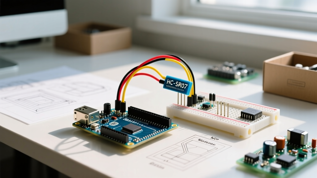
If you have spent any time in the embedded electronics space, you have inevitably encountered the HC-SR04. It is the quintessential arduino sonic sensor, favored for its low cost and straightforward 4-pin interface. However, as makers and engineers transition to more complex environments and modern 3.3V microcontrollers like the ESP32-S3 or Raspberry Pi RP2040, the HC-SR04 and its countless 2026 market clones have revealed significant architectural flaws. From infinite loop hangs to phantom distance readings, troubleshooting this ultrasonic module requires a deep understanding of acoustic physics, power delivery, and logic-level translation.
This guide bypasses the basic "how-to-wire" tutorials and dives straight into advanced diagnostic frameworks, hardware failure modes, and software optimizations to stabilize your ultrasonic measurements.
The Anatomy of a Timeout: Why Your Code Hangs
The most frequent complaint regarding the HC-SR04 is the microcontroller freezing. This is almost always caused by the pulseIn() function. When you send a 10-microsecond HIGH pulse to the Trigger pin, the sensor emits an eight-cycle 40kHz ultrasonic burst and pulls the Echo pin HIGH. It then waits for the sound wave to bounce back. Once the echo is detected, the Echo pin drops LOW.
But what happens if the sound wave is absorbed by acoustic foam, deflects off an angled glass surface, or simply exceeds the 4-meter maximum range? The Echo pin never drops LOW. By default, the Arduino pulseIn() reference documentation notes that the function will wait indefinitely (up to several seconds depending on the core implementation) before timing out, effectively blocking your main loop and crashing real-time tasks like motor control or Wi-Fi stacking.
The Software Fix: Enforcing a Hard Timeout
You must explicitly define a timeout threshold in microseconds. Since sound travels at roughly 343 meters per second in air at 20°C, a round trip of 4 meters (the sensor's absolute physical limit) takes approximately 23.3 milliseconds (23,300 microseconds). Setting a timeout of 25,000 microseconds guarantees the function will abort if the target is out of range, returning a 0 instead of hanging your MCU.
// VULNERABLE: Will hang indefinitely if no echo is received
long duration = pulseIn(echoPin, HIGH);

// ROBUST: Times out after 25ms (approx 4.25 meters)
long duration = pulseIn(echoPin, HIGH, 25000);

if (duration == 0) {
    // Handle out-of-bounds or acoustic absorption error
    Serial.println("Error: Acoustic timeout or out of range");
} else {
    float distance_cm = (duration * 0.0343) / 2.0;
}
Hardware Failure Mode 1: Power Rail Sag and Decoupling
A widespread issue in 2026 DIY builds is powering the HC-SR04 directly from a microcontroller's onboard 3.3V or 5V LDO regulator via long breadboard jumper wires. During the 40kHz ultrasonic burst, the piezoelectric transducers and the onboard driver circuitry (often a cloned MAX232 equivalent) draw a transient current spike of up to 15mA to 20mA.
If your power rail has high impedance due to thin wires or a weak LDO, this transient draw causes a localized voltage sag. The internal oscillator relies on a stable VCC to maintain the precise 40kHz frequency. A voltage drop shifts the frequency, causing the receiver transducer to ignore the returning echo because it is listening outside the narrow 40kHz bandpass.
Expert Troubleshooting Step: Solder a 100nF (0.1µF) ceramic capacitor directly across the VCC and GND pins on the back of the HC-SR04 PCB to handle high-frequency transients. For long cable runs (over 1 meter), add a 47µF to 100µF electrolytic capacitor at the sensor end to stabilize the baseline voltage.
Hardware Failure Mode 2: The 3.3V Logic Trap
The HC-SR04 is fundamentally a 5V device. While it can sometimes trigger on a 3.3V logic HIGH from an ESP32, the Echo pin will output a full 5V HIGH when the echo is received. Feeding 5V into a 3.3V-tolerant GPIO pin on an RP2040 or ESP32-S3 will degrade the silicon over time, leading to phantom interrupts, increased pin leakage current, and eventual permanent GPIO death.
To safely interface the Echo pin with modern 3.3V microcontrollers, you must implement a voltage divider. As detailed in the SparkFun voltage divider tutorial, using a 1kΩ resistor (R1, connected to Echo) and a 2kΩ resistor (R2, connected to GND) will step the 5V output down to a safe ~3.33V.
Environmental Physics: Temperature Compensation
Most basic tutorials hardcode the speed of sound to 343 m/s. This is only accurate at 20°C (68°F). If your arduino sonic sensor is deployed in an unheated garage in winter (e.g., 0°C) or a hot greenhouse (e.g., 35°C), your distance calculations will drift by up to 6%, which equates to a 12cm error on a 2-meter measurement.
According to standard acoustic physics models outlined by Wikipedia's Speed of Sound documentation, the speed of sound in dry air scales linearly with temperature. You can compensate for this in software by integrating a cheap TMP36 or BME280 sensor.
Dynamic Compensation Formula
float temperature_C = 20.0; // Replace with BME280 reading
float speedOfSound = 331.3 + (0.606 * temperature_C); // m/s
float cmPerMicrosecond = speedOfSound / 10000.0; // Convert to cm/µs

float distance_cm = (duration * cmPerMicrosecond) / 2.0;
Diagnostic Matrix: Symptoms and Solutions
Use this rapid-reference table to diagnose erratic behavior in the field.
| Symptom | Root Cause | Hardware / Software Fix |
|---|---|---|
Constant 0 or Timeout |
Acoustic absorption, angled target, or missing timeout parameter. | Add 25000µs timeout; ensure target is flat and perpendicular within a 15° cone. |
| Random Massive Spikes (e.g., 4000cm) | 40kHz Cross-talk from nearby sensors or EMI from brushed DC motors. | Stagger trigger pulses by 50ms; physically separate sensors by >30cm. |
| Readings Drift Over Time | Transducer silver mesh oxidation or ambient temperature shifts. | Apply thin conformal coating to mesh; implement software temp compensation. |
| ESP32/RP2040 Random Reboots | 5V Echo pin back-feeding into 3.3V rail via internal protection diodes. | Install 1kΩ/2kΩ voltage divider on the Echo line immediately. |
When to Abandon the HC-SR04: 2026 Upgrade Paths
While the HC-SR04 costs roughly $1.20 to $1.50 in today's market, its bare-PCB design and 5V dependency make it unsuitable for harsh or precision environments. If you have exhausted the troubleshooting steps above and still face reliability issues, consider upgrading to one of these modern alternatives.
Component Comparison Chart
| Sensor Model | Avg. Price (2026) | Interface | Best Use Case |
|---|---|---|---|
| HC-SR04 | $1.30 | Analog Pulse (5V) | Basic indoor robotics, educational kits. |
| JSN-SR04T | $3.80 | Analog Pulse (3.3V-5V) | Outdoor applications, liquid level sensing (IP67 waterproof probe). |
| RCWL-1601 | $4.20 | I2C / UART / PWM | Precision industrial IoT, multi-sensor arrays (no pulseIn blocking). |
| US-015 | $2.50 | Analog Pulse (3.3V-5V) | Drop-in HC-SR04 replacement requiring native 3.3V logic support. |
Final Verdict on Ultrasonic Troubleshooting
Mastering the arduino sonic sensor ecosystem requires looking past the basic wiring diagrams. By enforcing strict software timeouts, stabilizing the power delivery network with proper decoupling capacitors, and respecting the logic-level thresholds of modern 3.3V microcontrollers, you can transform the erratic HC-SR04 into a highly reliable peripheral. When environmental constraints demand more, upgrading to an I2C-based module like the RCWL-1601 eliminates the timing vulnerabilities of analog pulse measurements entirely, freeing your MCU to handle the heavy computational lifting of your 2026 embedded projects.