
Mastering the LM35 Temperature Sensor with Arduino
When building environmental monitors, weather stations, or thermal protection circuits, choosing the right sensor is critical. The Texas Instruments LM35 series remains a staple in the maker and engineering communities. Unlike digital sensors that require complex communication protocols like I2C or 1-Wire, the LM35 is a precision analog sensor that outputs a voltage directly proportional to the Celsius temperature. This makes interfacing the LM35 temperature sensor with Arduino incredibly straightforward, especially for beginners looking to understand analog-to-digital conversion (ADC).
In this comprehensive 2026 guide, we will cover exact hardware specifications, wiring topologies, the underlying ADC mathematics, and advanced noise-filtering techniques to ensure your readings are lab-grade accurate.
Hardware Breakdown: Part Numbers and 2026 Pricing
Before wiring anything, it is vital to know that "LM35" is a family of sensors. If you are sourcing components from authorized distributors like Mouser or DigiKey, you will encounter specific part numbers. Avoid unbranded clones from generic marketplaces, as they often suffer from severe calibration drift.
- LM35DZ/NOPB (TO-92 Package): The standard version. Accuracy of ±0.5°C at room temperature. Measures 2°C to 150°C. Current pricing is approximately $1.85 per unit.
- LM35CAZ/NOPB (TO-92 Package): The high-precision version. Accuracy of ±0.25°C at room temperature. Measures -40°C to 110°C. Current pricing is approximately $3.50 per unit.
- LM35DT/NOPB (TO-220 Package): Designed for mounting directly to heat sinks for chassis temperature monitoring. Priced around $2.95.
Note: For standard breadboard prototyping, the LM35DZ/NOPB in the TO-92 package is the most cost-effective and widely used choice.
Pinout and Wiring Topology
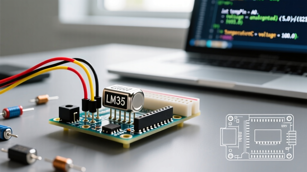
The TO-92 package has three pins. When viewing the sensor with the flat face pointing toward you and the leads pointing downward, the pinout from left to right is:
- VCC (Pin 1): Connect to Arduino 5V.
- VOUT (Pin 2): Connect to Arduino Analog Pin (e.g., A0).
- GND (Pin 3): Connect to Arduino GND.
⚠️ CRITICAL WARNING: Reverse Polarity Destruction
The LM35 has very low reverse-polarity tolerance. If you accidentally swap VCC and GND, the sensor will draw excessive current, overheat instantly (reaching >100°C in seconds), and permanently destroy the silicon die. Always double-check the flat-face orientation before applying power.
Wiring for Arduino Uno R3 vs. Uno R4
While the physical wiring remains identical, the underlying microcontroller architecture changes how we process the signal. The classic Arduino Uno R3 (ATmega328P) uses a 10-bit ADC, yielding 1024 discrete steps over 5V. The newer Arduino Uno R4 Minima/WiFi (Renesas RA4M1) features a 14-bit ADC, yielding 16,384 steps. We will address how to handle this in the code section to maximize resolution.
The Mathematics of Analog Conversion
The LM35 outputs 10mV per degree Celsius. To convert the raw ADC integer into a usable temperature, we must map the digital steps back to voltage, and then to temperature.
For a standard 5V Arduino with a 10-bit ADC:
- Voltage per step = 5.0V / 1024 = 4.88mV
- Temperature (°C) = (Raw ADC Value × 4.88mV) / 10mV
- Simplified: Temperature (°C) = Raw ADC Value × 0.488
This linear relationship eliminates the need for complex Steinhart-Hart equations required by NTC thermistors, making the LM35 highly efficient for microcontroller processing.
Arduino C++ Code with Moving Average Filter
Analog signals are susceptible to electromagnetic interference (EMI). A single analogRead() might fluctuate by ±3 steps due to ambient noise. To solve this, we implement a software moving average filter. Furthermore, this code includes a conditional check to leverage the 14-bit ADC if you are using an Arduino Uno R4.
// LM35 Temperature Sensor with Arduino - Noise Filtered
const int sensorPin = A0;
const int numReadings = 20; // Sample size for moving average
float readings[numReadings];
int readIndex = 0;
float total = 0;
float averageTemp = 0;

void setup() {
  Serial.begin(9600);

  // Initialize array
  for (int i = 0; i < numReadings; i++) {
    readings[i] = 0;
  }

  // Uncomment the line below if using Arduino Uno R4 for 14-bit resolution
  // analogReadResolution(14);
}

void loop() {
  // Subtract the last reading
  total = total - readings[readIndex];

  // Read the analog pin
  int rawADC = analogRead(sensorPin);

  // Calculate voltage and temperature based on 10-bit (default) or 14-bit
  // Assuming 10-bit (1024) for standard Uno R3 compatibility
  float voltage = rawADC * (5.0 / 1024.0);
  float tempC = voltage * 100.0; // 10mV per degree C

  readings[readIndex] = tempC;
  total = total + readings[readIndex];
  readIndex = readIndex + 1;

  if (readIndex >= numReadings) {
    readIndex = 0;
  }

  averageTemp = total / numReadings;

  Serial.print("Smoothed Temperature: ");
  Serial.print(averageTemp);
  Serial.println(" °C");

  delay(500); // Update twice per second
}
Sensor Comparison Matrix: LM35 vs Alternatives
Is the LM35 the right choice for your specific project? Compare it against other popular beginner sensors to make an informed hardware decision.
| Feature | TI LM35DZ (Analog) | Analog Devices TMP36 (Analog) | Maxim DS18B20 (Digital) |
|---|---|---|---|
| Interface | Analog Voltage (10mV/°C) | Analog Voltage (10mV/°C + 500mV offset) | 1-Wire Digital |
| Measurement Range | 2°C to 150°C | -40°C to 125°C | -55°C to 125°C |
| Typical Accuracy | ±0.5°C (at 25°C) | ±1°C (at 25°C) | ±0.5°C (-10°C to +85°C) |
| Wiring Complexity | Low (3 wires) | Low (3 wires) | Medium (Requires 4.7kΩ pull-up) |
| Best Use Case | Room/Chassis temp monitoring | Sub-zero environmental tracking | Waterproof probes, long-distance runs |
Pro-Tips for Lab-Grade Accuracy
Beginners often report that their LM35 readings "jump around" or read 2-3 degrees higher than a commercial thermometer. Here is how to eliminate those edge cases and failure modes.
1. Hardware Low-Pass Filtering
The output impedance of the LM35 is very low (around 0.1Ω), but long breadboard wires act as antennas, picking up 50/60Hz mains hum and high-frequency switching noise from nearby DC motors or displays. The Fix: Solder a 0.1µF (100nF) ceramic capacitor directly between the VOUT and GND pins as close to the sensor body as possible. This creates a hardware low-pass filter that drastically stabilizes the ADC readings before they even reach the Arduino.
2. Mitigating Self-Heating Errors
According to the official TI LM35 Datasheet, the sensor draws approximately 114µA of quiescent current. In still air, this causes a self-heating error of about 0.08°C. While negligible for most DIY projects, if you are measuring thermal gradients in a sealed, low-airflow enclosure, this self-heating will skew your baseline. Ensure adequate, albeit gentle, airflow across the TO-92 package for maximum accuracy.
3. The Negative Temperature Limitation
A standard single-supply LM35 circuit (VCC to 5V, GND to GND) cannot read below 2°C. The output pin cannot swing below the ground reference. If your project requires monitoring freezing temperatures (e.g., a DIY freezer thermostat), you must either use the LM35CAZ with a dual-power supply circuit (involving a negative voltage rail and pull-down resistors) or switch to a TMP36 or DS18B20, which natively support sub-zero readings on a single 3.3V/5V rail.
Troubleshooting Common Interfacing Issues
- Readings are stuck at 0°C or 500°C: Check your wiring. A reading of ~500°C usually means the ADC pin is floating (disconnected wire) or reading the full 5V rail due to a short between VCC and VOUT.
- Temperature slowly climbs over time: You are likely experiencing thermal coupling. If the LM35 is placed too close to the Arduino's onboard 5V linear voltage regulator, the ambient heat from the regulator will bleed into the sensor. Move the sensor at least 15cm away from the main microcontroller board using twisted-pair or shielded cable.
- Erratic jumps of ±5°C: Your USB power source is noisy. Cheap, unbranded USB wall adapters introduce massive switching noise onto the 5V rail, which directly alters the ADC reference voltage. Power the Arduino via a high-quality, regulated power supply or use the Arduino's 3.3V pin as the
analogReference(EXTERNAL)for a cleaner baseline.
Final Thoughts
Interfacing the LM35 temperature sensor with Arduino is a foundational skill that bridges the gap between theoretical electronics and practical embedded programming. By understanding the ADC math, respecting the hardware pinout, and implementing both hardware and software filtering, you can extract highly reliable, precision thermal data for your 2026 IoT and robotics projects. For deeper dives into microcontroller analog peripherals, consult the Arduino Analog Reference Documentation to explore advanced ADC prescaler adjustments.