
Mastering Ultrasonic Sensor Integration in 2026
When makers and engineers set out to code ultrasonic sensor Arduino circuits, they often stop at the first tutorial they find. While a basic ping sketch is fine for a weekend robot, real-world applications like industrial tank monitoring, precision agriculture, or autonomous navigation demand robust, error-handling code. Ultrasonic sensors are notoriously susceptible to acoustic shadowing, temperature drift, and cross-talk. In this comprehensive integration guide, we will move beyond beginner tutorials and explore production-ready C++ implementations for the two most dominant ultrasonic modules on the market: the classic pulse-echo HC-SR04 and the industrial-grade UART A02YYUW.
Hardware Selection Matrix: Pulse/Echo vs. UART
Before writing a single line of code, you must match the sensor's communication protocol and physical characteristics to your environment. As of 2026, the market has largely consolidated around three primary form factors for DIY and prosumer Arduino projects.
| Model | Interface | Range & Beam Angle | Blind Zone | Avg. Price (2026) | Best Use Case |
|---|---|---|---|---|---|
| HC-SR04 | Pulse/Echo (GPIO) | 2cm - 400cm / 15° | ~2cm | $2.50 - $4.00 | Indoor robotics, basic object avoidance |
| JSN-SR04T V2.0 | Pulse/Echo (GPIO) | 20cm - 450cm / 60° | ~20cm | $8.00 - $11.00 | Outdoor environments, wide-area detection |
| A02YYUW | UART (Serial) | 3cm - 450cm / 75° | ~3cm | $12.00 - $15.00 | Liquid level sensing, harsh/wet environments |
Deep Dive 1: Coding the HC-SR04 (Pulse/Echo Protocol)
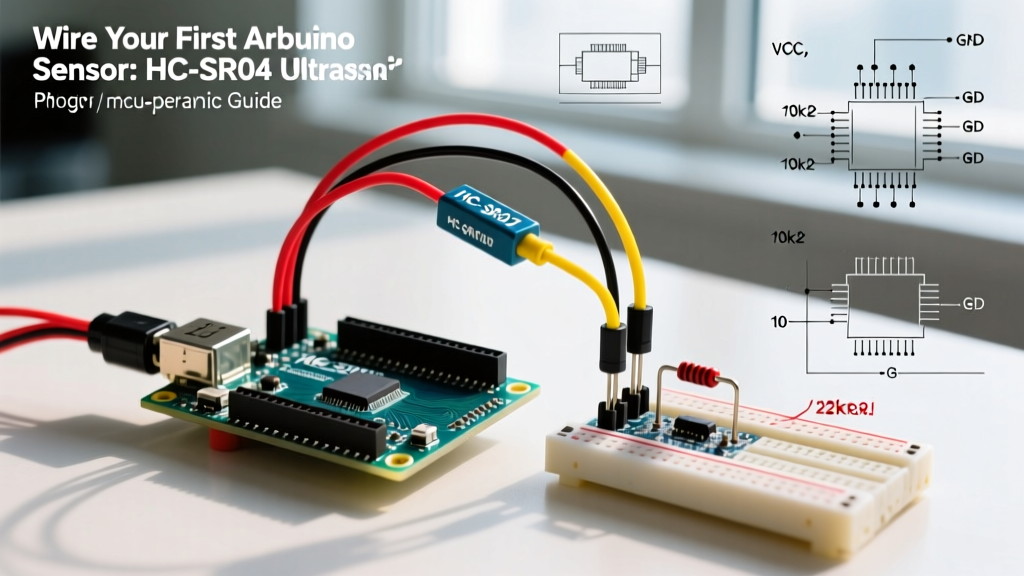
The HC-SR04 operates on a simple time-of-flight (ToF) principle. You send a 10-microsecond HIGH pulse to the Trigger pin, and the module emits an 8-cycle 40kHz ultrasonic burst. It then pulls the Echo pin HIGH until the sound wave returns. The distance is calculated by measuring the duration of the HIGH state on the Echo pin.
The Problem with Blocking Code
Most beginner guides use the Arduino pulseIn() function without a timeout parameter. If the sound wave scatters off a curved surface and never returns, pulseIn() will block your main loop for up to 1 second (its default timeout), completely freezing your robot or control system.
Production-Ready HC-SR04 Implementation
To prevent loop blocking, we enforce a strict 30,000-microsecond (30ms) timeout. Since sound travels roughly 58.2µs per centimeter (round-trip), a 30ms timeout safely covers the sensor's maximum theoretical range of ~500cm while returning control to the microcontroller quickly if no echo is detected.
const int trigPin = 9;
const int echoPin = 10;
const long TIMEOUT_US = 30000; // 30ms timeout

void setup() {
  pinMode(trigPin, OUTPUT);
  pinMode(echoPin, INPUT);
  Serial.begin(115200);
}

long getDistanceCM() {
  // Clear the trigger pin
  digitalWrite(trigPin, LOW);
  delayMicroseconds(2);

  // Send 10us pulse
  digitalWrite(trigPin, HIGH);
  delayMicroseconds(10);
  digitalWrite(trigPin, LOW);

  // Read echo with timeout
  long duration = pulseIn(echoPin, HIGH, TIMEOUT_US);

  if (duration == 0) {
    return -1; // Return -1 to indicate timeout/no echo
  }

  return duration / 58.2;
}

void loop() {
  long distance = getDistanceCM();
  if (distance != -1) {
    Serial.print("Distance: ");
    Serial.println(distance);
  } else {
    Serial.println("Error: Acoustic shadow or out of range.");
  }
  delay(50); // 20Hz polling rate
}
Deep Dive 2: Coding the A02YYUW (UART Protocol)
For applications involving water tanks, outdoor weather exposure, or high electromagnetic interference (EMI), the A02YYUW is the superior choice. Unlike the HC-SR04, it processes the time-of-flight internally and outputs a continuous stream of 4-byte data packets via UART (Serial). This completely frees your Arduino's GPIO pins from microsecond-level timing constraints.
Parsing the 4-Byte UART Packet
The A02YYUW data frame consists of a Header (0xFF), Data High Byte, Data Low Byte, and a Checksum. The checksum is the sum of the first three bytes, masked to 8 bits. When utilizing Arduino Serial communication, you must implement a state machine or a rolling buffer to ensure you don't lose byte alignment, which is a common failure mode in noisy environments.
unsigned char data_buffer[4] = {0};
unsigned char checksum;
unsigned int distance_mm;

void setup() {
  Serial.begin(115200); // Debug output
  Serial1.begin(9600);  // A02YYUW Hardware Serial (e.g., Arduino Mega or ESP32)
}

void loop() {
  if (Serial1.available() > 0) {
    delay(4); // Wait for the 4-byte packet to arrive in buffer

    if (Serial1.available() == 4) {
      for (int i = 0; i < 4; i++) {
        data_buffer[i] = Serial1.read();
      }

      // Validate Header
      if (data_buffer[0] == 0xFF) {
        // Calculate Checksum
        checksum = (data_buffer[0] + data_buffer[1] + data_buffer[2]) & 0x00FF;

        // Verify Checksum
        if (checksum == data_buffer[3]) {
          distance_mm = (data_buffer[1] << 8) | data_buffer[2];
          Serial.print("Valid Distance (mm): ");
          Serial.println(distance_mm);
        } else {
          Serial.println("Checksum Error: EMI interference suspected.");
        }
      }
    }
  }
}
Pro-Tip for ESP32 Users: If you are using an ESP32 instead of a classic ATmega328P, avoid SoftwareSerial. The ESP32's Wi-Fi and Bluetooth interrupts frequently cause software serial timing jitter, resulting in dropped bytes from the A02YYUW. Always map the sensor to one of the ESP32's hardware UART pins (e.g., UART1 or UART2).
Advanced Edge Cases & Environmental Compensation
Writing the code is only 50% of the battle. The physics of sound introduces variables that naive code fails to account for.
1. Temperature Drift Compensation
The speed of sound in air is not a constant 343 m/s; it is highly dependent on ambient temperature. According to engineering thermodynamics data, the speed of sound increases by approximately 0.606 m/s for every 1°C rise in temperature. If your Arduino project operates in an unheated garage in winter (5°C) and a hot greenhouse in summer (45°C), the speed of sound shifts from 334 m/s to 358 m/s. This introduces a massive 7.2% measurement error if uncalibrated.
The Fix: Integrate a DS18B20 or BME280 temperature sensor and apply this dynamic formula to your HC-SR04 duration:
float tempC = 20.0; // Read from BME2, speedMps = 331.3 + (0.606 * tempC);
float distanceCM = (duration / 2.0) * (speedMps / 10000.0);
2. Acoustic Ghosting and the Median Filter
When an ultrasonic wave hits a corrugated surface or a chain-link fence, it creates multipath reflections. The sensor might return a valid but entirely incorrect "ghost" distance. A standard moving average filter will not protect you from this, as a single massive outlier will skew the average.
Instead, implement a Median Filter. By taking 5 rapid readings, sorting them, and selecting the middle value, you mathematically guarantee the rejection of up to 2 extreme outliers per cycle without introducing the phase lag associated with large moving averages.
3. Multi-Sensor Cross-Talk
If you are deploying three HC-SR04 sensors on a single rover, firing them simultaneously will result in Sensor A reading the echo from Sensor B's ultrasonic burst.
- Hardware Solution: Use a multiplexer (like the 74HC4051) to route echoes.
- Software Solution: Stagger the trigger pulses. Fire Sensor 1, wait 30ms for the acoustic energy to dissipate, then fire Sensor 2. A 30ms delay guarantees that even at maximum range, the previous burst has completely decayed.
Summary
Successfully coding an ultrasonic sensor for an Arduino project requires moving past simple copy-paste sketches. By enforcing strict timeouts on pulse-echo sensors, validating checksums on UART modules, and applying07, 2026