
The Architecture of Modern Arduino LCD Interfacing
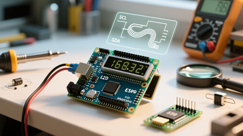
Interfacing character LCDs with microcontrollers has evolved significantly over the last decade. While the Hitachi HD44780 controller remains the undisputed industry standard for 16x2 and 20x4 character displays, the physical wiring paradigm has shifted. In 2026, writing parallel LCD display code for Arduino using six digital GPIO pins is largely relegated to legacy repair jobs and extreme low-latency edge cases. The modern standard utilizes I2C serial backpacks based on the PCF8574 I/O expander, reducing the wiring footprint to just four pins (VCC, GND, SDA, SCL) while freeing up critical microcontroller resources.
However, this hardware simplification introduces software complexity. The transition from parallel to I2C requires robust driver libraries capable of handling bus arbitration, address translation, and pin-mapping variations. This guide dissects the underlying architecture of I2C LCD backpacks and provides a definitive framework for writing optimized, non-blocking LCD display code for Arduino projects.
Hardware Prerequisites: Understanding the PCF8574 Backpack
Before writing a single line of code, you must understand the silicon bridging your Arduino to the LCD. The I2C backpack soldered to the back of a standard 1602A or 2004A module uses an 8-bit I/O expander. There are two primary variants in circulation, and confusing them is the root cause of 90% of initialization failures:
- PCF8574T (NXP/TI): Base I2C address is
0x20. With the standard A0, A1, A2 jumper pads bridged high, the resulting address is0x27. - PCF8574AT: Base I2C address is
0x38. With the same jumper configuration, the resulting address is0x3F.
According to the NXP PCF8574 datasheet, the chip lacks internal pull-up resistors for the I2C bus. While the Arduino's internal pull-ups exist, they are often too weak (20kΩ-50kΩ) to maintain signal integrity on the 400kHz I2C fast-mode bus, especially if your wiring exceeds 15cm.
2026 Hardware Pro-Tip: Always install external 4.7kΩ pull-up resistors on the SDA and SCL lines when using I2C LCD backpacks. Relying on the ATmega328P's internal pull-ups frequently results in corrupted bytes and 'white block' initialization failures on the LCD.
Library Showdown: LiquidCrystal_I2C vs. hd44780
When developers search for LCD display code for Arduino, they are typically directed to the legacy LiquidCrystal_I2C library by Frank de Brabander. While functional, it is fundamentally flawed for modern development workflows due to its reliance on hardcoded addresses and rigid pin mappings. The undisputed gold standard in 2026 is the hd44780 library by Bill Perry, which treats the LCD as an abstracted peripheral rather than a hardcoded pin array.
| Feature | LiquidCrystal_I2C (Legacy) | hd44780_I2Cexp (Modern Standard) |
|---|---|---|
| Address Detection | Manual (Hardcoded in setup) | Automatic (Probes I2C bus on boot) |
| Pin Mapping | Manual (Requires bitwise mapping) | Automatic (Detects backpack wiring) |
| Multiple Displays | Clunky (Requires separate instances) | Native (Auto-indexes multiple addresses) |
| Diagnostics | None | Built-in I2CexpDiag sketch |
| Execution Speed | Standard blocking delays | Optimized busy-flag polling |
Writing Optimized LCD Display Code for Arduino
To leverage the auto-detection and busy-flag polling of the hd44780 library, you must use the hd44780_I2Cexp I/O class. This class communicates via the Arduino Wire library but bypasses the crude delay-based timing of older drivers. By reading the HD44780's busy flag (BF) over the I2C bus, the microcontroller knows exactly when the LCD's internal DDRAM is ready for the next byte, eliminating the need for arbitrary delay() calls.
Core Implementation Sketch
#include <Wire.h>
#include <hd44780.h>
#include <hd44780ioClass/hd44780_I2Cexp.h>

// Instantiate the LCD object; auto-detects address and pin mapping
hd44780_I2Cexp lcd;

// Define LCD geometry
const int LCD_COLS = 16;
const int LCD_ROWS = 2;

void setup() {
  // Initialize the Wire library for I2C communication
  Wire.begin();

  // Optional: Drop I2C clock to 100kHz if using long cables (>30cm)
  // Wire.setClock(100000);

  // Initialize LCD (auto-probes bus for PCF8574/PCF8574A)
  int status = lcd.begin(LCD_COLS, LCD_ROWS);

  if (status != 0) {
    // Handle initialization failure (e.g., blink onboard LED)
    hd44780::fatalError(status);
  }

  lcd.print("ElectricalFlux");
  lcd.setCursor(0, 1);
  lcd.print("I2C Driver Guide");
}

void loop() {
  // Non-blocking update logic goes here
}
Memory Management: DDRAM vs. CGRAM
Advanced LCD display code for Arduino requires understanding the controller's memory architecture. The HD44780 features two distinct memory regions:
- DDRAM (Display Data RAM): Holds the ASCII characters currently visible on the screen. Writing to DDRAM is what
lcd.print()does. - CGRAM (Character Generator RAM): A volatile 64-byte memory bank used to store up to eight custom 5x8 pixel characters. Because CGRAM is volatile, custom characters must be redefined if the LCD loses power or undergoes a hard reset.
To render custom telemetry icons (like battery levels or signal bars), define a byte array in PROGMEM to save SRAM, then push it to CGRAM during setup().
Hardware-Level Troubleshooting & Failure Modes
Even with perfect code, I2C LCD integrations frequently fail at the physical layer. Use this diagnostic matrix to resolve common edge cases without rewriting your firmware.
1. The 'Row 1 White Blocks' Failure
Symptom: The top row displays solid white blocks; the bottom row is blank. The backlight is on.
Root Cause: Power (VCC/GND) is reaching the module, but the I2C initialization sequence failed. The HD44780 defaults to 8-bit mode on power-up. If the I2C handshake fails, the library cannot send the command to switch it to 4-bit mode.
Solution: Run an I2C scanner sketch. If the device does not appear at 0x27 or 0x3F, check your solder joints on the PCF8574 header pins. Verify that SDA is connected to A4 and SCL to A5 (on Uno/Nano form factors).
2. The 'Blank Screen' Contrast Issue
Symptom: The screen is completely blank, but the I2C scanner confirms the backpack is present and responding.
Root Cause: The V0 (contrast) pin voltage is incorrect. The blue trimpot on the backpack adjusts the voltage differential between VDD and V0.
Solution: Use a precision Phillips screwdriver to turn the trimpot counter-clockwise until the pixel matrix becomes faintly visible, then back off slightly. Note: 3.3V LCD modules require a negative voltage on V0, which standard 5V backpacks cannot provide without a charge pump circuit.
3. I2C Bus Lockups and Ghosting
Symptom: The LCD displays garbled text, or the entire I2C bus crashes, taking down other sensors (like BME280 or MPU6050).
Root Cause: Bus capacitance exceeds the I2C specification (typically >400pF), causing signal rise times to degrade. The PCF8574 misinterprets noise as data bytes.
Solution: Add 4.7kΩ pull-up resistors to both SDA and SCL lines. If the issue persists, lower the I2C bus speed to 50kHz using Wire.setClock(50000); before calling lcd.begin().
Conclusion
Writing robust LCD display code for Arduino in 2026 means abandoning legacy parallel libraries and hardcoded I2C addresses. By leveraging the hd44780 library's auto-probing capabilities and respecting the physical limitations of the PCF8574 I/O expander, you can create resilient, non-blocking user interfaces that survive the electrical noise and bus capacitance inherent in real-world DIY enclosures.