
The Gold Standard for Microcontroller Telemetry
When building your first sensor node, environmental monitor, or robotic dashboard, outputting data to the serial monitor quickly becomes impractical. You need a standalone visual interface. Enter the Arduino LCD display—specifically, the 16x2 character LCD based on the legendary Hitachi HD44780 controller. While OLED and TFT screens have surged in popularity, the 16x2 LCD remains the undisputed champion for beginners in 2026 due to its extreme durability, wide operating temperature range (-20°C to 70°C), and ultra-low cost.
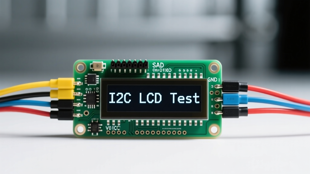
However, wiring a raw 16x2 LCD in parallel mode requires 6 GPIO pins and a messy web of jumper wires. The modern solution is the I2C backpack. By attaching a PCF8574 I/O expander chip to the back of the display, you reduce the wiring to just four pins: VCC, GND, SDA, and SCL. This tutorial will walk you through the exact hardware selection, wiring topology, I2C address discovery, and C++ programming required to get your Arduino LCD display running flawlessly.
Parallel vs. I2C: Why the Backpack Matters
Before we wire anything, it is crucial to understand why the I2C backpack is the mandatory choice for modern Arduino projects. The I2C (Inter-Integrated Circuit) protocol allows multiple devices to share just two data wires, freeing up your microcontroller's limited GPIO pins for actual sensors and actuators.
| Feature | Parallel (Direct Wiring) | I2C (With Backpack) |
|---|---|---|
| GPIO Pins Required | 6 (RS, EN, D4, D5, D6, D7) | 2 (SDA, SCL) |
| Wiring Complexity | High (prone to loose connections) | Low (standard 4-pin JST or Dupont) |
| Bus Expandability | None (1 display per set of pins) | Up to 8 displays on one I2C bus |
| Code Library | LiquidCrystal (Built-in) | LiquidCrystal_I2C (Third-party) |
2026 Hardware BOM & Pricing
To follow this tutorial, you will need a few specific components. Pricing reflects the current 2026 market for hobbyist electronics:
- Microcontroller: Arduino Uno R4 Minima or R4 WiFi (~$22 - $28). The classic Uno R3 is also perfectly compatible.
- Display Module: 16x2 Character LCD with pre-soldered I2C backpack. Generic HD44780 clones cost between $3.50 and $6.00 on Amazon or AliExpress. For higher quality, the DFRobot DFR0063 or Adafruit 714 retail for $12.00 to $16.00 and feature superior backlight diffusion.
- Wiring: 4x Female-to-Male Dupont jumper wires (24 AWG stranded).
- Power Supply: A dedicated 5V 2A USB wall adapter. (Do not rely on your laptop's USB port for high-brightness backlights).
Step-by-Step Wiring Guide
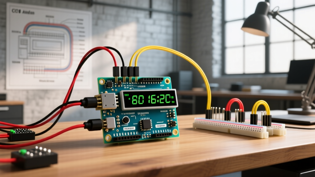
The I2C bus uses open-drain architecture, meaning it requires a common ground and specific data lines. Here is the exact pinout for connecting your Arduino LCD display to an Uno R3 or R4:
- GND (Ground): Connect the backpack's GND pin to any of the Arduino's GND pins.
- VCC (Power): Connect the backpack's VCC pin to the Arduino's 5V pin. Warning: Do not connect this to 3.3V. The HD44780 logic and the 16x2 LED backlight require 4.5V to 5.5V to operate correctly.
- SDA (Serial Data): Connect to the Arduino's SDA pin. On the Uno R3, this is A4. On the Uno R4, use the dedicated SDA pin on the right-side header.
- SCL (Serial Clock): Connect to the Arduino's SCL pin. On the Uno R3, this is A5. On the Uno R4, use the dedicated SCL pin.
⚡ Voltage Logic Warning for 3.3V Boards: If you are adapting this tutorial for an ESP32, Arduino Nano 33 IoT, or Raspberry Pi Pico, you are dealing with 3.3V logic. While the PCF8574 I2C expander can technically be powered by 3.3V, the LCD backlight will be extremely dim. For 3.3V microcontrollers, use a bidirectional I2C logic level shifter (like the BSS138-based modules costing ~$1.50) and power the LCD VCC from a separate 5V rail.
Finding Your I2C Address: The 0x27 vs 0x3F Dilemma
The most common point of failure for beginners is assuming the I2C address. The NXP PCF8574 datasheet specifies that the base address is determined by the state of three address pins (A0, A1, A2) on the chip. Most cheap backpacks ground these pins, resulting in an address of 0x27. However, many manufacturers use the PCF8574A variant, which shifts the base address to 0x3F.
Instead of guessing, upload the standard I2C Scanner sketch (available via the Arduino IDE Examples menu) to your board. Open the Serial Monitor at 9600 baud. The scanner will poll the bus and return the exact hexadecimal address of your display. Write this address down; you will need it for the code.
Programming the Arduino LCD Display
To drive the display, we use the LiquidCrystal_I2C library by Frank de Brabander, available via the Arduino Library Manager. Below is a robust, production-ready template that initializes the display, prints static text, and updates a dynamic sensor value without causing screen flicker.
#include <Wire.h>
#include <LiquidCrystal_I2C.h>

// Initialize the library with the I2C address and display dimensions
// Change 0x27 to 0x3F if your I2C scanner indicated that address
LiquidCrystal_I2C lcd(0x27, 16, 2);

// Custom character: Degree symbol
byte degreeSymbol[8] = {
  0b00110,
  0b01001,
  0b01001,
  0b00110,
  0b00000,
  0b00000,
  0b00000,
  0b00000
};

void setup() {
  Wire.begin();
  lcd.init();
  lcd.backlight();

  // Load custom character into slot 0
  lcd.createChar(0, degreeSymbol);

  lcd.setCursor(0, 0);
  lcd.print("Electrical Flux");
  lcd.setCursor(0, 1);
  lcd.print("System Ready...");
  delay(2000);
  lcd.clear();
}

void loop() {
  // Simulate reading a temperature sensor (e.g., AHT20 or DHT22)
  float tempC = analogRead(A0) * (5.0 / 1023.0) * 10.0;

  // Update only the changing data to prevent LCD flicker
  lcd.setCursor(0, 0);
  lcd.print("Temp: ");
  lcd.print(tempC, 1);
  lcd.write(0); // Print custom degree symbol
  lcd.print("C   "); // Trailing spaces overwrite old characters

  delay(500);
}
Understanding the Anti-Flicker Technique
Notice the trailing spaces in the lcd.print("C "); line. A common beginner mistake is calling lcd.clear() inside the loop() function. Clearing the screen takes several milliseconds and causes a visible, annoying flicker. By simply overwriting the old characters with blank spaces, you achieve a smooth, professional-looking UI update.
Advanced Troubleshooting & Edge Cases
Even with perfect code, hardware anomalies can derail your project. Here is how to diagnose the most common Arduino LCD display failures, drawing on years of field diagnostics:
1. The "White Boxes" or Blank Screen Issue
If your backlight is on but you only see a row of solid white (or dark) blocks, or nothing at all, your contrast is misconfigured. On the back of the I2C backpack is a small blue trimpot (a 10kΩ variable resistor). Use a small Phillips screwdriver to turn this pot clockwise or counter-clockwise until the characters become sharply visible against the background. If turning the pot does nothing, verify that the backpack's VCC pin is actually receiving 4.8V or higher using a multimeter.
2. I2C Bus Lockups and Ghosting
The I2C protocol requires pull-up resistors on the SDA and SCL lines to pull the voltage high when no device is actively pulling it low. According to the Arduino Wire Library Documentation, the internal pull-ups of the ATmega328P are often too weak (20kΩ - 50kΩ) for reliable I2C communication over cables longer than 10cm. Furthermore, ultra-cheap 2025/2026 clone backpacks frequently omit the 4.7kΩ pull-up resistors to save fractions of a cent. If your display randomly freezes or prints gibberish, solder two 4.7kΩ resistors between the SDA/SCL pins and the 5V VCC pin on the backpack.
3. Backlight Dimming and Brownouts
The LED backlight on a standard 16x2 display draws between 20mA and 40mA, while the logic circuit draws about 2mA. If you are also powering a Wi-Fi module (like the ESP8266) or a servo motor from the same Arduino 5V rail, you can easily exceed the 500mA limit of a standard PC USB port. When the voltage sags below 4.5V, the HD44780 controller will brownout, resulting in frozen text or a completely dead display. Always use a dedicated 5V 2A wall adapter plugged into the Arduino's barrel jack or USB-C port for projects with multiple peripherals.
4. The Missing Backlight Jumper
Many I2C backpacks feature a two-pin header with a small black jumper cap located near the PCF8574 chip. This jumper physically connects the 5V rail to the LCD's backlight anode (pin 15). If you remove this jumper, the display will function and print text, but the backlight will remain completely off. If your screen looks incredibly dark in normal room lighting, check that this jumper cap is securely in place.
Further Reading & Authoritative References
To deepen your understanding of character displays and I2C communication protocols, consult the following industry resources:
- Adafruit Character LCDs Guide - An excellent visual breakdown of the HD44780 pinout and internal memory mapping.
- NXP PCF8574 I/O Expander Datasheet - Essential reading for understanding I2C addressing and current sinking capabilities.
- Arduino Wire (I2C) Library Documentation - The official reference for I2C bus speeds, buffer limits, and pull-up resistor requirements.
Mastering the Arduino LCD display is a rite of passage for embedded systems hobbyists. By leveraging the I2C backpack, handling address conflicts gracefully, and writing non-blocking UI code, you transform a basic component into a robust telemetry dashboard ready for real-world deployment.