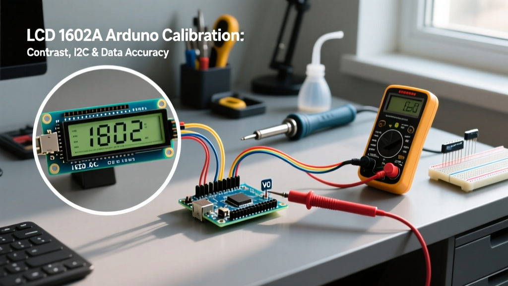

The Science of LCD 1602A Arduino Calibration
When integrating a standard LCD 1602A Arduino setup into a microcontroller project, most beginners stop at wiring the pins and uploading a basic 'Hello World' sketch. However, as a senior electronics engineer, I can tell you that out-of-the-box modules rarely deliver optimal readability or data accuracy without precise calibration. The ubiquitous 1602A display, driven by the Hitachi HD44780 controller, requires careful tuning of its analog contrast voltage (V0), exact I2C address mapping, and strict timing management to prevent data flickering and truncation.
In 2026, while high-resolution OLEDs and TFTs are common, the 1602A remains a staple in industrial control panels, DIY weather stations, and bench power supplies due to its ruggedness and low cost (typically $2.50 to $4.00 per unit). This guide bypasses basic wiring tutorials and dives deep into the calibration and accuracy parameters required to make your LCD 1602A Arduino integration professional-grade.
Analog Calibration: Nailing the V0 Contrast Voltage
The most common point of failure in LCD 1602A deployments is improper contrast calibration. The V0 pin (Pin 3) dictates the liquid crystal twist angle by setting a voltage relative to VSS (Ground). If V0 is too high, the screen appears blank; if it is too low, you get 'black boxes' or severe ghosting.
The Problem with Standard Potentiometers
Most starter kits include a 10kΩ trimpot for V0. While functional, mechanical potentiometers are prone to vibration-induced drift and oxidation over time, leading to contrast degradation in field-deployed Arduino sensors. For permanent installations, I strongly recommend replacing the trimpot with a fixed resistor voltage divider calibrated to your specific display's backlight chemistry.
| Backlight Color | Target V0 Voltage (Relative to GND) | Recommended Resistor Divider (R1 / R2) | Typical Operating Temp Range |
|---|---|---|---|
| Yellow-Green (Standard) | 0.8V - 1.1V | 1.5kΩ / 1kΩ | -10°C to +60°C |
| Blue (White Text) | 0.4V - 0.6V | 2.2kΩ / 470Ω | 0°C to +50°C |
| Red / RGB Modules | 0.9V - 1.2V | 1.2kΩ / 1kΩ | -20°C to +70°C |
Pro-Tip for Temperature Compensation: Liquid crystal viscosity changes with temperature. If your Arduino project operates in unheated garages or outdoor enclosures, wire a 1kΩ NTC thermistor in parallel with R2. This creates a passive temperature-compensated contrast circuit that automatically lowers V0 as temperatures drop, preventing the 'black box' freeze effect common in sub-zero environments.
I2C Address Accuracy: PCF8574 vs. PCF8574A Mapping
When using an I2C backpack to save Arduino GPIO pins, address accuracy is paramount. A frequent troubleshooting nightmare occurs when developers assume all I2C backpacks share the same default address. In reality, manufacturers use two different I/O expander chips, each with a distinct base address architecture.
- PCF8574 (Standard): Base address is
0x20. With A0, A1, A2 jumper pads open (pulled high), the default address is0x27. - PCF8574A (Alternative): Base address is
0x38. With jumper pads open, the default address is0x3F.
According to the Texas Instruments PCF8574 Datasheet, the address pins (A0-A2) dictate the lower three bits of the I2C slave address. If your Arduino Wire library fails to initialize the display, it is almost always an address mismatch, not a wiring fault.
Calibrating the I2C Bus for Signal Integrity
The I2C protocol relies on open-drain outputs. Many cheap LCD 1602A I2C backpacks omit the mandatory pull-up resistors on the SDA and SCL lines, relying entirely on the Arduino's internal weak pull-ups (approx. 30kΩ - 50kΩ). This results in slow rise times and data corruption at higher bus speeds.
Hardware Fix: Always solder a 4.7kΩ pull-up resistor from SDA to VCC (5V) and another 4.7kΩ from SCL to VCC on the backpack header. This ensures sharp signal edges and allows you to safely increase the I2C clock speed to 400kHz (Fast Mode) in your Arduino sketch using
Wire.setClock(400000);, drastically reducing display refresh latency.
Data Accuracy: Formatting Sensor Outputs Without Truncation
Displaying sensor data (e.g., from a BME280 or DS18B20) accurately on a 16-column grid requires strict string formatting. The standard lcd.print(float_val) function in the Arduino LiquidCrystal_I2C library defaults to two decimal places, but it dynamically allocates memory and can cause heap fragmentation on AVR-based boards like the Uno or Nano.
The dtostrf() Method for Precision
For deterministic memory usage and exact decimal alignment, calibrate your data output using the C-standard dtostrf() function. This converts floating-point numbers to strings with explicit width and precision parameters before sending them to the DDRAM (Display Data RAM).
Here is the exact implementation for printing a calibrated temperature reading with one decimal place, right-aligned in a 5-character block:
char tempBuffer[6];
// dtostrf(float_val, min_width, precision, buffer)
dtostrf(bme.readTemperature(), 5, 1, tempBuffer);
lcd.setCursor(11, 0);
lcd.print(tempBuffer);
This guarantees that a reading of 9.5 prints as _ _9.5 (where _ is a space), preventing the text-shifting jitter that occurs when values cross from single to double digits. For deeper integration with the Arduino Wire and display libraries, refer to the official Arduino Wire Reference.
Timing Calibration: Eliminating Ghosting and Flicker
A hallmark of an amateur LCD 1602A Arduino project is a flickering screen. This is caused by the misuse of the lcd.clear() command inside the main loop(). The HD44780 controller requires approximately 1.52 milliseconds to execute a clear command. If called every 100ms during a sensor polling cycle, the display spends nearly 2% of its time blank, causing visible flicker and accelerating backlight LED degradation.
Selective Overwriting Technique
Instead of clearing the screen, calibrate your loop to selectively overwrite only the changing digits. If a sensor value drops from 1023 to 99, simply printing 99 leaves the trailing 23 on the screen, resulting in 9923.
The Calibration Fix: Always print a string padded with trailing spaces, or print spaces immediately after your data string to 'erase' previous longer values.
| Method | Execution Time | Flicker Risk | DDRAM Wear Impact |
|---|---|---|---|
lcd.clear() in Loop |
1.52 ms per call | High (Visible Flicker) | High (Constant reset) |
| Selective Overwrite | ~0.05 ms per char | None (Zero Flicker) | Minimal (Targeted writes) |
Edge Case Troubleshooting Matrix
Even with perfect code, hardware anomalies can disrupt accuracy. Use this matrix to diagnose edge cases in your LCD 1602A Arduino build:
| Symptom | Root Cause | Calibration / Hardware Fix |
|---|---|---|
| Top row shows solid white boxes | Controller failed to initialize; RW pin floating. | Tie RW (Pin 5) strictly to GND. Ensure 5V rail is stable under load. |
| Random characters / Japanese glyphs | DDRAM pointer overflow; writing past 40-byte line buffer. | Implement strict lcd.setCursor() bounds checking before printing. |
| Display works on Uno, fails on ESP32 | Logic level mismatch; ESP32 outputs 3.3V, LCD expects 5V TTL. | Use a bi-directional logic level converter (e.g., BSS138 MOSFET circuit) on SDA/SCL. |
| Faint text, backlight is bright | V0 voltage too close to GND; insufficient bias. | Adjust V0 voltage divider. Blue screens require V0 near 0.5V, not 0V. |
Frequently Asked Questions (FAQ)
Can I calibrate the LCD 1602A backlight brightness via software?
Standard I2C backpacks do not support software PWM for the backlight because the LED anode is hardwired to VCC through a jumper. To achieve software-calibrated brightness, you must remove the 'LED' jumper on the backpack and wire the anode pin to an Arduino PWM pin (e.g., Pin 9). Use analogWrite() to calibrate the brightness, but ensure you use a transistor (like a 2N2222) to handle the current, as the backlight can draw up to 120mA, which exceeds safe microcontroller GPIO limits.
Why does my custom character (CGRAM) disappear after a few hours?
Custom characters are stored in the HD44780's CGRAM (Character Generator RAM), which is volatile and can be corrupted by electrical noise or improper I2C bus termination. If your Arduino environment has heavy EMI (e.g., near relay modules or stepper motors), CGRAM data can degrade. The professional calibration standard is to rewrite the custom character arrays to CGRAM periodically (e.g., once every 60 seconds) or immediately after any lcd.clear() command, which resets the memory pointers.
Is the LiquidCrystal_I2C library still the best choice in 2026?
While SparkFun and other educators historically recommended the standard LiquidCrystal_I2C library, modern embedded development favors the HD44780 library by Bill Perry (available via the Arduino Library Manager). It features auto-detection of I2C addresses and pin mappings, effectively eliminating the PCF8574 vs PCF8574A address calibration errors mentioned earlier in this guide. It also handles I2C bus timeouts gracefully, preventing your Arduino from freezing if the display is physically disconnected during operation.
By treating the LCD 1602A not just as a dumb output device, but as a precision peripheral requiring voltage, timing, and data formatting calibration, you elevate your Arduino projects from hobbyist prototypes to reliable, field-ready instruments.