
The Great Debate: Arduino Servo H-Bridge vs. Dedicated PWM Drivers
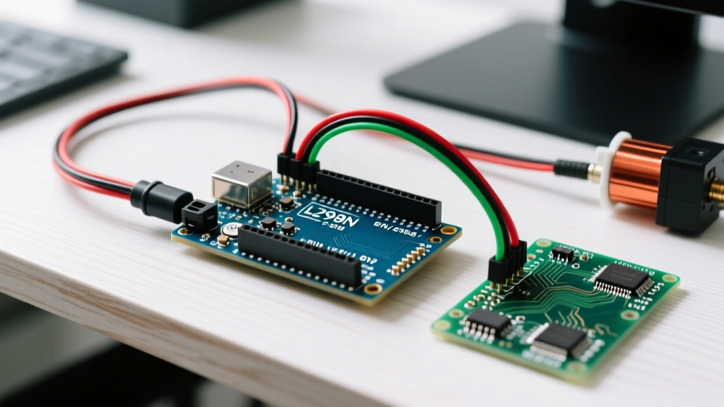
When building robotic arms, hexapods, or automated camera gimbals, one of the most frequent hardware questions we encounter on the bench is whether you can use an Arduino servo H-bridge configuration to control standard positional servos. It is a completely understandable point of confusion for beginners transitioning from DC motor control to precision actuator control. After all, if an L298N or DRV8833 H-bridge can drive a motor forward and backward, why not use it for a servo?
The short answer is: you should not use an H-bridge for standard positional servos. Doing so will result in severe signal jitter, component overheating, and potentially catastrophic failure of the servo's internal feedback loop. In 2026, with the availability of ultra-cheap, high-resolution I2C PWM drivers, the architectural choice is clearer than ever. This guide breaks down the electrical engineering realities behind the Arduino servo H-bridge misconception and compares it directly against the industry-standard PCA9685 PWM driver.
Expert Insight: An H-bridge is designed to reverse voltage polarity across a two-wire DC load. A standard three-wire RC servo requires a constant DC voltage supply and a precise, unipolar 50Hz PWM timing signal on its third wire. Mixing these two paradigms is a fundamental mismatch in peripheral interfacing.
Understanding the Signal: Why H-Bridges Fail at Servo Control
To understand why an H-bridge is the wrong tool for the job, we must look at the anatomy of a standard hobby servo (like the ubiquitous SG90 or the high-torque MG996R). According to the Pololu RC Servo Selection Guide, a standard positional servo expects a very specific pulse train:
- Frequency: 50Hz (one pulse every 20 milliseconds).
- Pulse Width: Between 500µs (0 degrees) and 2500µs (180 degrees), with 1500µs as the center neutral point.
- Voltage: A steady 4.8V to 6.0V DC on the red (VCC) wire.
An H-bridge controls speed and direction by modulating the power rails themselves, often using high-frequency PWM (1kHz - 20kHz) to simulate lower voltages. If you attempt to wire a servo's power lines through an H-bridge, you are either reversing its polarity (which will instantly fry the internal potentiometer and control IC) or feeding it high-frequency noise that the internal comparator cannot decode.
What About Continuous Rotation Servos?
Continuous rotation servos (like the FS90R) are essentially geared DC motors with an internal driver board. While they can technically be driven by feeding constant power to the VCC/GND pins and sending an H-bridge modulated signal to the signal wire, it is highly inefficient. You lose the precise speed control that native 50Hz PWM provides, and you waste the H-bridge's current-handling capabilities on a low-current logic signal.
Component Breakdown: The H-Bridge (L298N / DRV8833)
H-bridges are phenomenal for their intended purpose: driving DC gear motors and bipolar stepper motors. Let us look at their specifications in the context of general robotics.
L298N (BJT Darlington Based)
- Price (2026 Market): $2.50 - $4.00 per module.
- Max Current: 2A per channel (3A peak).
- Voltage Drop: ~1.5V to 2.0V. This is a massive drawback. If you feed it 5V, your output is only ~3.2V, which is below the stall voltage of most standard servos.
- Verdict for Servos: Completely unsuitable. The voltage drop alone will cause high-torque servos to chatter and reset the Arduino via brownout.
DRV8833 / DRV8871 (MOSFET Based)
- Price: $1.50 - $3.00 per module.
- Voltage Drop: ~0.2V (much better efficiency).
- Verdict for Servos: Still unsuitable for positional control. While it solves the voltage drop issue, it still lacks the hardware timing generators required to output a clean 50Hz, 500-2500µs pulse without bogging down the Arduino's CPU timers.
Component Breakdown: PCA9685 16-Channel PWM Driver
The PCA9685 is an I2C-bus controlled LED controller that has been universally adopted by the maker and robotics community as the ultimate servo driver. As detailed in the NXP PCA9685 Datasheet, this chip features 16 hardware-timed PWM channels, completely offloading the timing burden from your microcontroller.
Key Architectural Advantages
- Hardware PWM Generation: The Arduino only needs to send an I2C command (e.g.,
setPWM(channel, 0, pulse_length)). The PCA9685 handles the 50Hz timing in the background. You can control 16 servos while your Arduino runs complex inverse kinematics or computer vision algorithms without a single microsecond of jitter. - 12-Bit Resolution: With 4096 steps per 20ms cycle, each step represents roughly 4.88µs. This translates to sub-degree precision on a standard 180-degree servo.
- Separated Power Rails: The breakout boards feature separate terminal blocks for
VCC(I2C logic power, 3.3V-5V) andV+(Servo power, up to 10V). This allows you to safely run 7.4V High-Voltage (HV) servos without frying your Arduino's logic pins.
Head-to-Head Comparison Matrix
| Feature | H-Bridge (L298N / DRV8833) | PCA9685 PWM Servo Driver |
|---|---|---|
| Primary Use Case | DC Motors, Stepper Motors | Positional & Continuous Servos, LEDs |
| Control Interface | GPIO + Hardware Timers (PWM) | I2C Bus (Addressable) |
| CPU Overhead | High (Requires constant timer interrupts) | Near Zero (Hardware timed) |
| Signal Output | Bipolar Voltage Reversal | Unipolar 50Hz Pulse Width Modulation |
| Max Channels per Module | 2 (L298N) / 2 (DRV8833) | 16 (Chainable up to 62 boards) |
| Avg. Module Cost (2026) | $2.50 - $4.00 | $4.50 - $7.00 |
| High-Voltage Servo Support | No (Limited by logic voltage) | Yes (V+ terminal accepts up to 10V) |
Critical Edge Cases & Hardware Integration (2026 Standards)
Choosing the PCA9685 over an H-bridge is only the first step. Real-world robotics builds in 2026 demand rigorous power management. Here are the edge cases that separate amateur builds from reliable deployments.
1. The Brownout Capacitor Rule
High-torque metal-gear servos (like the 20kg DS3218) can draw upward of 2.5 Amps during stall or rapid directional changes. The standard 1000µF electrolytic capacitor included on most cheap PCA9685 breakout boards is insufficient for more than three or four of these servos. When the voltage dips below 4.5V, the servo's internal logic resets, causing the arm to spasm violently.
The Fix: Add a low-ESR 4700µF to 10,000µF capacitor directly across the V+ and GND terminal blocks on the PCA9685. For hexapods using 12+ servos, use a dedicated BEC (Battery Eliminator Circuit) rated for 10A continuous, bypassing the PCB traces entirely and injecting power directly into a custom bus bar.
2. Logic Level Translation (3.3V vs 5V)
If you are driving the PCA9685 with a 5V Arduino Uno, you can wire the I2C lines directly. However, if you are using a 3.3V microcontroller (like the ESP32 or Raspberry Pi Pico), you must be careful. The Adafruit 16-Channel PWM Servo Driver Guide notes that while the PCA9685 I2C lines are generally 5V tolerant, feeding 5V into the VCC pin of the breakout board when the I2C pull-ups are tied to a 3.3V logic bus can cause communication timeouts. Always power the VCC logic pin with the same voltage as your microcontroller's I2C bus, and reserve the V+ terminal strictly for the high-current servo power.
3. I2C Address Collisions
If your robot requires more than 16 servos, you will need to daisy-chain multiple PCA9685 boards. The board features 6 address jumper pads (A0 through A5). By soldering these pads, you can assign unique hexadecimal addresses (from 0x40 to 0x7F). Never leave address pads partially bridged with flux residue, as this creates parasitic resistance that leads to ghosting—where two servos on different boards twitch simultaneously.
Final Verdict: Which Should You Wire Up?
The idea of an Arduino servo H-bridge is a relic of early DIY experimentation where makers tried to force DC motor drivers to do the job of signal generators. For any modern application requiring positional accuracy, smooth kinematics, and CPU efficiency, the H-bridge is entirely obsolete for servo control.
Invest the $5 to $7 in a PCA9685 breakout board. It will save you hours of debugging timer interrupts, protect your microcontroller from inductive voltage spikes, and provide the sub-degree precision required for advanced robotics. Reserve your L298N and DRV8833 H-bridges for the tank treads and conveyor belts on your chassis, and let the I2C PWM drivers handle the joints.