
The Architecture of Arduino PWM Pins: Why They Aren't All Equal
When beginners write analogWrite(pin, 128), they often assume this universally translates to a 50% duty cycle at a standard frequency across all microcontrollers. In reality, Arduino PWM pins are deeply tied to the underlying hardware timers of the specific silicon on the board. A value of 128 means 50% on an 8-bit ATmega328P, but it means just 3% duty cycle on a 12-bit Renesas RA4M1. Furthermore, the default frequencies—often hovering around 490Hz—can cause audible whine in DC motors and visible stepping in low-brightness LED dimming.
As of 2026, the maker ecosystem has expanded far beyond the classic 8-bit AVR chips. With the introduction of the Uno R4 Minima and the dominance of the ESP32-S3 for peripheral control, choosing the right board requires a strict comparison of PWM resolution, timer mappings, and hardware limitations. This guide breaks down the exact PWM architectures of the most popular Arduino-compatible boards to help you match the right silicon to your sensors, motors, and displays.
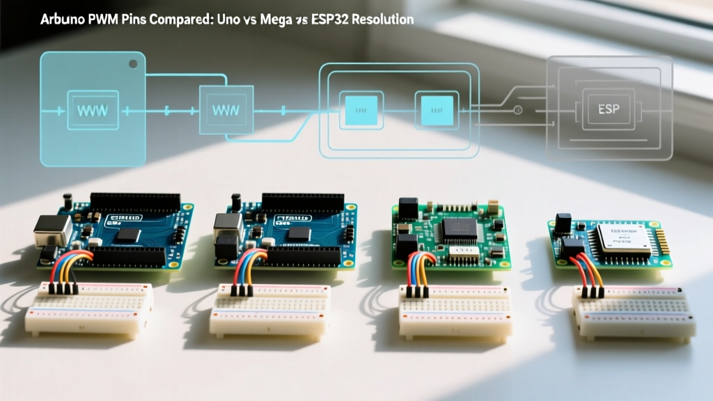
Board-by-Board PWM Comparison Matrix
| Board (2026 Standard) | MCU Core | PWM Channels | Default Resolution | Max Hardware Resolution | Default Base Freq | Logic Level |
|---|---|---|---|---|---|---|
| Uno R3 / Nano | ATmega328P (8-bit AVR) | 6 | 8-bit (0-255) | 16-bit (Timer1) | 490 Hz (980 Hz on 5,6) | 5V |
| Mega 2560 | ATmega2560 (8-bit AVR) | 15 | 8-bit (0-255) | 16-bit | 490 Hz | 5V |
| Uno R4 Minima | Renesas RA4M1 (Cortex-M4) | 6 (mapped) | 8-bit (0-255) | 12-bit (0-4095) | 490 Hz | 3.3V (5V tolerant) |
| Due | SAM3X8E (Cortex-M3) | 12 | 8-bit (0-255) | 12-bit (0-4095) | 1000 Hz | 3.3V |
| ESP32-S3 | Xtensa LX7 (Dual-Core) | 16 (LEDC) | 8-bit (0-255) | 20-bit (0-1048575) | 5000 Hz | 3.3V |
ATmega328P (Uno R3 & Nano): The 8-Bit Baseline and Timer Conflicts
The classic ATmega328P offers 6 hardware PWM pins: 3, 5, 6, 9, 10, and 11. These are driven by three internal timers (Timer0, Timer1, and Timer2). While sufficient for basic heater control or simple 5V relay PWM, the architecture is riddled with edge cases that catch intermediate makers off guard.
The Timer0 Trap and SPI Conflicts
Pins 5 and 6 are tied to Timer0, which the Arduino core uses to track time for millis(), delay(), and micros(). If you attempt to change the PWM frequency on these pins by modifying the TCCR0B prescaler registers to eliminate motor whine, you will instantly break all time-based functions in your sketch.
Furthermore, Pin 11 is tied to Timer2, but it also serves as the MOSI line for the SPI bus. If you are wiring up an SPI-based TFT display or an SD card module while simultaneously trying to output PWM on Pin 11, the hardware will conflict, resulting in corrupted data transfers or erratic PWM duty cycles. Rule of thumb: Never use Pin 11 for PWM if the SPI bus is active.
For high-frequency motor control (16kHz–25kHz to avoid acoustic noise), you must abandon analogWrite() and configure Timer1 (Pins 9 and 10) in Phase and Frequency Correct mode using the ICR1 register. Setting the prescaler to 1 and ICR1 to 400 yields exactly 20kHz, but limits your resolution to roughly 10 bits (0-400).
ATmega2560 (Mega 2560): More Pins, Same 8-Bit Bottleneck
The ATmega2560 expands the PWM count to 15 pins (2-13 and 44-46). Despite the higher pin count, it relies on the exact same 8-bit AVR timer architecture as the Uno. The primary advantage of the Mega is timer redundancy. Because it features six timers (Timer0 through Timer5), you can dedicate Timer3 or Timer4 exclusively to high-frequency motor control without risking conflicts with the SPI bus, Serial ports, or the millis() clock.
Failure Mode Warning: When driving high-capacitance loads (like long LED strips) directly from Mega PWM pins without a logic-level MOSFET, the 490Hz switching frequency combined with the pin's ~40mA current limit can cause localized brownouts in the ATmega2560, leading to random I2C bus lockups. Always use a dedicated gate driver like the TC4427 for loads exceeding 20mA.
Uno R4 Minima & Due: Stepping into 12-Bit and True DAC
The transition to 32-bit ARM Cortex microcontrollers fundamentally changed peripheral control. The Arduino Due (SAM3X8E) was the first to introduce 12-bit PWM resolution (0-4095) and true hardware DAC pins (DAC0, DAC1). However, the Due's 3.3V logic requires level shifters for standard 5V motor drivers, adding BOM cost and wiring complexity.
In 2026, the Uno R4 Minima (Renesas RA4M1) is the preferred upgrade path. It maintains the classic 5V-tolerant form factor while offering 32-bit processing. By calling analogWriteResolution(12) in your setup, you unlock 12-bit PWM on its mapped pins. This is critical for LED dimming applications; human vision perceives brightness logarithmically, meaning an 8-bit (255 step) PWM signal will show visible 'stepping' or flickering in the bottom 10% of the brightness range. A 12-bit signal provides 4096 steps, allowing for ultra-smooth gamma-corrected fades.
ESP32-S3 (Arduino Framework): The LEDC Powerhouse
When designing complex sensor arrays or multi-channel motor controllers, the ESP32-S3 is the undisputed king of PWM. It abandons traditional AVR timers in favor of the LEDC (LED Control) peripheral. The Espressif LEDC API allows you to independently configure up to 16 channels with custom resolutions and frequencies.
The Resolution vs. Frequency Trade-off (APB Clock Limits)
The ESP32's PWM is derived from the 80 MHz APB clock. There is a strict mathematical inverse relationship between your desired frequency and your maximum resolution. The formula is:
Max Freq = 80,000,000 / (2^resolution)
- For 20kHz Motor Control: Max resolution is 11-bit (2048 steps). Setup:
ledcSetup(channel, 20000, 11); - For 12-bit LED Dimming: Max frequency drops to 19,531 Hz. Setup:
ledcSetup(channel, 19531, 12); - For 50Hz Servo Control: You can push resolution to 16-bit (65536 steps) for micro-stepping continuous rotation servos.
Edge Case: If you attempt to set a 16-bit resolution alongside a 20kHz frequency using the Arduino ledc wrapper, the underlying ESP-IDF will silently truncate the resolution or throw a runtime warning in the serial monitor, resulting in a duty cycle that ignores your lower bits. Always calculate the APB limit before initializing your channels.
Selecting the Right Board for Specific Peripherals
Choosing your microcontroller should be dictated by the physical requirements of the peripheral you are wiring:
- DC Motors & Solenoids: Require 16kHz to 25kHz frequencies to push the switching noise above human hearing. Winner: ESP32-S3 (native 11-bit at 20kHz) or ATmega328P (only if you manually hack Timer1 registers).
- High-Fidelity LED Dimming: Require >12-bit resolution to avoid low-end stepping, and frequencies above 1kHz to prevent camera flicker (PWM aliasing). Winner: Uno R4 Minima or ESP32-S3.
- Analog Sensor Simulation: If you need to output a true DC voltage (e.g., simulating a 0-5V thermocouple signal for an industrial PLC), PWM with an RC filter is insufficient due to ripple. Winner: Arduino Due or Uno R4 Minima, utilizing their dedicated hardware DAC pins.
References and Further Reading
- Arduino Official Language Reference: analogWrite() and Timer Mappings
- Espressif IoT Development Framework: LEDC Peripheral API Documentation
- Microchip Technology: ATmega2560 Datasheet and Timer Architecture