
Why the Right L298N to Arduino Library Matters
Despite the proliferation of modern MOSFET-based motor drivers in 2026, the STMicroelectronics L298N dual full-bridge module remains a staple in DIY robotics and microcontroller prototyping. Priced between $3.50 and $6.00 per module, its accessibility is unmatched. However, successfully bridging the gap from hardware to software requires more than just copying basic digitalWrite commands. When connecting an l298n to arduino environments, selecting the right driver library and understanding the underlying Pulse Width Modulation (PWM) logic is critical for achieving smooth acceleration, precise speed mapping, and active braking.
This guide moves beyond elementary blink-and-spin tutorials. We will dissect the electrical realities of the L298N chip, compare the top Arduino libraries available for motor control, and provide production-ready code structures for advanced directional and speed management.
The Hardware Reality: BJT Voltage Drop and Wiring
Before diving into software libraries, you must account for the L298N's internal architecture. Unlike modern TI DRV8871 or TB6612FNG drivers that use efficient MOSFETs, the L298N relies on internal NPN Bipolar Junction Transistors (BJTs). According to the STMicroelectronics L298N Datasheet, this BJT design introduces a combined voltage drop of approximately 1.8V to 2.0V across the internal switching junctions.
Expert Insight: If you supply 6V to the L298N's VCC terminal, your DC motor will only receive ~4V. To drive a standard 6V motor at its rated speed, you must supply at least 8V to the module and compensate for the 2V drop in your software mapping logic.
Essential Wiring Matrix for PWM Control
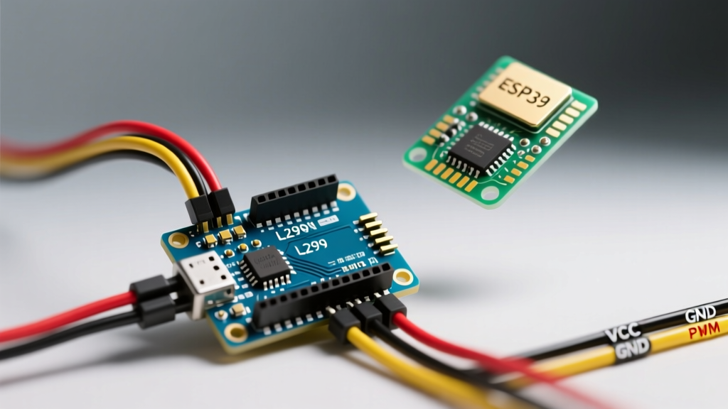
To utilize any advanced library, your hardware pins must be mapped to Arduino pins that support hardware PWM (denoted by the ~ symbol on the Uno/Nano). Below is the optimal wiring configuration for dual DC motor control.
| L298N Pin | Arduino Uno/Nano Pin | Function & Requirements |
|---|---|---|
| ENA | Pin 9 (~PWM) | Motor A Speed Control (PWM required) |
| IN1 | Pin 8 (Digital) | Motor A Logic Direction 1 |
| IN2 | Pin 7 (Digital) | Motor A Logic Direction 2 |
| ENB | Pin 10 (~PWM) | Motor B Speed Control (PWM required) |
| IN3 | Pin 6 (Digital) | Motor B Logic Direction 1 |
| IN4 | Pin 5 (Digital) | Motor B Logic Direction 2 |
| GND | GND | Critical: Must share common ground with Arduino |
| 12V / VCC | External PSU (+) | Motor Power Supply (7V - 35V) |
Top Libraries for L298N Motor Control in 2026
While you can manually toggle pins using native Arduino functions, encapsulating this logic into a library prevents code bloat and handles edge cases like PWM dead-zones. Here is a comparison of the primary driver libraries used by embedded engineers today.
| Library Name | Best Use Case | Stepper Support | Active Braking API |
|---|---|---|---|
| L298N (Lombardo) | DC Motors, clean API, ease of use | No | Yes (via brake() method) |
| AccelStepper | Stepper motors, acceleration profiles | Yes (Excellent) | N/A (Holding torque used) |
| Native (No Lib) | Memory-constrained ATtinys | Manual implementation | Manual pin toggling |
For standard DC motor robotics, Andrea Lombardo’s L298N Library on GitHub remains the gold standard due to its lightweight footprint and object-oriented approach.
Deep Dive: Implementing the Lombardo L298N Library
Let’s implement the library to control a single DC motor with speed mapping that compensates for the BJT voltage drop. As noted in the Arduino Official PWM Documentation, standard analogWrite outputs a 490Hz frequency on pins 9 and 10, which the L298N handles efficiently without excessive switching losses.
Code Implementation: Speed Mapping and Direction
#include <L298N.h>

// Pin definitions based on our wiring matrix
#define ENA 9
#define IN1 8
#define IN2 7

// Initialize Motor A object
L298N motorA(ENA, IN1, IN2);

void setup() {
  Serial.begin(115200);
  // Set initial speed (0-255)
  motorA.setSpeed(0);
}

void loop() {
  // 1. Forward Acceleration with Deadzone Compensation
  // Motors often stall below 2V. We map our desired 0-100%
  // input to a 60-255 PWM output to overcome the BJT drop.
  for (int i = 0; i <= 100; i++) {
    int pwmVal = map(i, 0, 100, 60, 255);
    motorA.setSpeed(pwmVal);
    motorA.forward();
    delay(50);
  }

  // 2. Active Braking (Fast Decay)
  motorA.brake();
  delay(1000);

  // 3. Reverse at fixed speed
  motorA.setSpeed(180);
  motorA.backward();
  delay(2000);

  // 4. Coast to stop (Slow Decay)
  motorA.stop();
  delay(1000);
}
Understanding the Code: Deadzone Compensation
The most critical concept in the code above is the map() function. Because of the 2V drop inherent to the L298N, sending a PWM value of 30 (roughly 0.6V on a 5V logic scale) will not overcome the internal transistor threshold or the motor's static friction. By mapping the user input to a minimum of 60, we ensure the motor immediately begins turning when commanded, eliminating the "stutter" effect common in beginner L298N to Arduino projects.
Advanced Driver Techniques: Braking vs. Coasting
A frequent point of confusion when wiring an l298n to arduino boards is the difference between stopping a motor and braking a motor. The L298N handles these via different logic states on the IN pins.
- Coasting (
motorA.stop()): Sets both IN1 and IN2 toLOW. The motor's terminals are effectively disconnected, and the motor spins down naturally due to mechanical friction. This is "Slow Decay". - Active Braking (
motorA.brake()): Sets both IN1 and IN2 toHIGHsimultaneously. This shorts the motor's back-EMF through the L298N's internal ground and VCC diodes, creating a magnetic counter-force that halts the rotor almost instantly. This is "Fast Decay".
Warning: Active braking generates a massive current spike back into the power supply rail. Ensure your external power supply has adequate bulk capacitance (e.g., a 470µF electrolytic capacitor across the VCC and GND terminals) to absorb this inductive kickback and prevent your Arduino from browning out.
Troubleshooting Common L298N to Arduino Driver Failures
Even with perfect code, hardware anomalies can disrupt motor control. Here are the most common edge cases encountered in the field:
- The Ground Loop Omission: The single most common reason an L298N fails to respond to Arduino logic signals is a missing common ground. The Arduino's 5V logic references its own GND. If the L298N GND is not tied to the Arduino GND, the IN pins see floating voltages, resulting in erratic spinning or total unresponsiveness.
- Audible PWM Whine: If your motor emits a high-pitched squeal, it is due to the Arduino's default 490Hz PWM frequency vibrating the motor coils. While changing timer registers to push the PWM to 31kHz can eliminate this, it is rarely necessary for hobbyist robotics and can interfere with the L298N's internal switching speeds.
- Onboard 5V Regulator Overheating: Most red L298N modules feature an onboard 7805 linear regulator to provide 5V to the logic chip. If you supply more than 12V to the main VCC terminal, this regulator must dissipate the excess voltage as heat. In 2026, best practice dictates removing the 5V jumper cap on the module and powering the logic side directly from the Arduino's 5V pin to prevent thermal shutdown.
FAQ: L298N Driver Nuances
Can I use the L298N to drive a single stepper motor?
Yes. The L298N is a dual H-bridge, which perfectly matches the two coil pairs (A+, A-, B+, B-) of a standard 4-wire bipolar stepper motor. You will need to use the AccelStepper library with the DRIVER interface type, wiring the coils to OUT1/OUT2 and OUT3/OUT4, while using the Arduino to sequence the IN1-IN4 pins.
Why is my motor only spinning in one direction?
This is almost always a wiring fault on the IN1/IN2 pins. If one of the digital pins is accidentally wired to an analog-only pin (like A0-A5 on an Uno) without using the correct digital mapping, or if a jumper wire is loose, the H-bridge cannot complete the reverse polarity circuit. Verify continuity on your logic wires.
Is the L298N still relevant compared to modern MOSFET drivers?
For high-efficiency, battery-powered robots, modern drivers like the TB6612FNG are vastly superior due to their low voltage drop. However, the L298N remains highly relevant for educational environments, high-voltage (up to 35V) test benches, and heavy-duty applications where its robust, physically large packaging can handle temporary current spikes better than surface-mount MOSFET alternatives.