
The Reality of Arduino and Laptop Screen Integration
Integrating a salvaged 15.6-inch laptop screen (such as the popular AUO B156HTN03.6 or LG LP156WF1) into an Arduino-based dashboard or data-logging project is a highly sought-after DIY milestone. However, a fundamental hardware barrier exists: standard microcontrollers like the ATmega328P (Arduino Uno) or even the ESP32 lack the native Timing Controllers (TCON) and high-speed differential signaling required to drive raw LVDS (Low-Voltage Differential Signaling) or eDP (Embedded DisplayPort) panels.
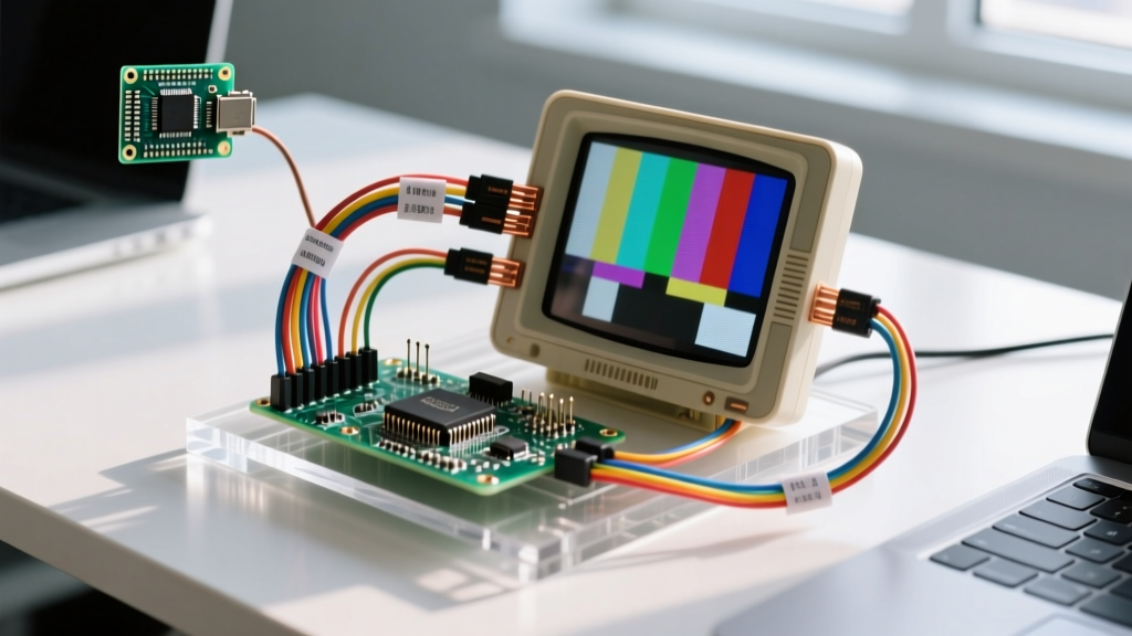
To bridge this gap, makers in 2026 rely on a two-tier architecture. The Arduino acts as the sensor aggregation hub, processing data and sending it via UART, I2C, or SPI to a secondary video bridge—typically an RTD2556VX HDMI-to-LVDS controller board paired with a Raspberry Pi or an advanced MCU like the Arduino Giga R1 WiFi. When your Arduino laptop screen setup fails, the issue rarely lies in the microcontroller code itself, but rather in the physical layer of the LVDS signaling, power delivery, or mapping protocols.
This troubleshooting guide bypasses basic coding errors and dives straight into the electrical and signal-integrity failure modes of laptop display integrations.
Diagnostic Matrix: Isolating the Failure Domain
Before grabbing a multimeter, use this diagnostic matrix to isolate whether your failure is occurring in the power delivery, the TCON board, or the LVDS data link.
| Symptom | Probable Domain | Multimeter Test Point | Expected Value |
|---|---|---|---|
| Completely dead (no backlight, no image) | Main Power / Inverter | Controller Board DC Input | 12.0V - 14.0V |
| Backlight ON, pitch black screen | TCON VCC / LVDS Cable | LVDS Connector Pins 1 & 2 | 3.3V (or 5.0V for older panels) |
| Colors inverted, split-screen, or heavy banding | LVDS Mapping / Bit Depth | N/A (Logic/Configuration) | N/A (Requires Jumper/OSD Fix) |
| Image flickers or shows digital noise | Signal Integrity / EMI | LVDS Differential Pairs | ~350mV swing (Oscilloscope) |
Top 4 Hardware Failure Modes & Solutions
1. The "Active Backlight, Black Screen" Syndrome
If the screen glows faintly (indicating the LED backlight inverter is receiving power) but no pixels render, the panel's internal TCON is starved of logic voltage. Modern 1080p laptop screens require exactly 3.3V on the VCC pins (usually pins 1, 2, and 3 on the 40-pin IPEX FFC connector).
- The Fix: Probe the VCC pins on the LCD side of the ribbon cable. If you read 0V, check the fuse on the LCD controller board. Many generic RTD2556VX boards ship with a 2A surface-mount fuse that blows if the LVDS cable is seated crookedly, shorting VCC to ground. Replace with a standard 1206 SMD fuse.
- Edge Case: Some older CCFL-backlit screens require 5V. If your controller board is hardwired for 3.3V, you must locate the VCC jumper on the PCB and bridge it to the 5V rail, otherwise the TCON will remain in an undervoltage lockout state.
2. Color Corruption: The VESA vs. JEIDA Mapping Conflict
This is the most common point of frustration when wiring an Arduino-driven HDMI bridge to a salvaged laptop screen. You power it on, and the display shows a split image, severe color banding, or a negative color palette. This is not a broken screen; it is a mismatch in LVDS data mapping standards.
According to Texas Instruments' LVDS signaling standards, data is serialized across differential pairs, but the industry uses two competing pinout formats for 8-bit color depth:
VESA Standard: Routes the most significant bits (MSBs) to the first data channel. Common in Dell and HP laptop panels.
JEIDA Standard: Routes the least significant bits (LSBs) to the first channel. Common in Lenovo and Acer panels.
- The Fix: Locate the 3-pin jumper header on your LCD controller board (usually labeled JEIDA/VESA or 8-BIT/6-BIT). Move the jumper to the alternate position. If your board lacks a physical jumper, use the IR service remote that came with the board, enter the factory menu (usually by pressing Menu + 1147), and toggle the LVDS Map setting.
3. Signal Degradation and EMI Flickering
LVDS operates by sending low-voltage differential signals (typically a 350mV swing) at high frequencies (up to 85MHz per pair for 1080p60). Because the voltage swing is so low, the signal is highly susceptible to Electromagnetic Interference (EMI) from nearby Arduino components, especially switching regulators and PWM motor drivers.
- The Failure: The screen displays random pixel snow, horizontal tearing, or drops the signal entirely when an Arduino-controlled relay clicks.
- The Fix: Never route the 40-pin LVDS FFC cable parallel to Arduino power wires or stepper motor leads. Keep the FFC cable under 15cm in length. If you must extend the distance between the controller board and the panel, use a shielded twisted-pair (STP) LVDS extension cable with a ferrite core clamp. Furthermore, ensure the metal chassis of the laptop screen is properly grounded to the DC power supply's earth pin to dissipate static buildup.
4. UART/Serial OSD Injection Failures
Many makers use an Arduino Uno or Nano to read sensors (e.g., BME280 temperature, current shunts) and push that data to the screen's On-Screen Display (OSD) via the controller board's UART RX pin. A common failure is the OSD displaying garbled characters or freezing.
- The Cause: Baud rate mismatch or logic level overvoltage. Most RTD2556VX OSD UART lines operate at 3.3V logic and expect 9600 or 115200 baud. The Arduino Uno outputs 5V logic, which can slowly degrade the controller board's RX optocoupler or logic gate.
- The Fix: Place a bidirectional logic level converter (like the BSS138-based Adafruit 4-channel shifter) between the Arduino TX pin and the LCD board RX pin. Verify the baud rate in your Arduino
Serial.begin()matches the factory OSD menu's UART setting.
2026 Hardware BOM & Cost Breakdown
Building a reliable Arduino laptop screen interface requires specific intermediary hardware. Below is a realistic 2026 Bill of Materials for a 15.6-inch 1080p integration.
| Component | Model / Specification | Est. Cost (2026) | Notes |
|---|---|---|---|
| LCD Controller Board | RTD2556VX (HDMI/VGA to LVDS) | $18.00 - $24.00 | Must match panel resolution via firmware |
| LVDS Ribbon Cable | 40-Pin IPEX (0.5mm pitch) | $4.50 - $7.00 | Check pin 1 orientation (red stripe) |
| Power Supply | 12V 4A DC (5.5x2.1mm barrel) | $12.00 - $15.00 | 4A required for 1080p LED backlights |
| Logic Level Shifter | BSS138 4-Channel I2C/UART | $3.00 - $5.00 | Mandatory for 5V Arduino to 3.3V TCON |
| MCU Bridge (Optional) | Arduino Giga R1 WiFi | $115.00 | Required if bypassing HDMI for direct RGB |
Advanced Tip: Reading the Panel Model Number
Never buy a controller board without first matching it to your exact panel model. The model number is printed on the back of the LCD metal chassis (e.g., B156HTN03.6 HW0A). The revision number (HW0A, HW1B) often dictates whether the panel uses standard LVDS or the newer eDP protocol. If your panel is eDP (common in 144Hz gaming laptop screens or 4K panels), a standard RTD2556VX LVDS board will not work. You must source an eDP-specific controller board (like those based on the RTD2556VX-eDP variant or the TS.MST1056.1), which typically costs $10 to $15 more and requires a specialized 30-pin or 40-pin eDP FFC cable with integrated lock latches.
Summary
Troubleshooting an Arduino laptop screen setup requires shifting your mindset from software debugging to high-speed signal integrity and power distribution. By verifying the 3.3V TCON logic, resolving VESA/JEIDA mapping conflicts, and protecting 3.3V UART lines from 5V Arduino logic, you can transform salvaged e-waste into a high-resolution, real-time telemetry dashboard.