
Essential Hardware for NEMA 17 Stepper Control
When you need precision rotational movement for CNC routers, 3D printers, or automated camera sliders, the NEMA 17 stepper motor paired with an A4988 driver remains the undisputed workhorse of the DIY electronics space. While silent drivers like the TMC2209 have gained traction in 2026 for audio-sensitive environments, the A4988 is still the most cost-effective and widely documented baseline for learning motion control. In this guide, we will break down exactly how to control stepper motor with Arduino, focusing on the NEMA 17 (specifically the 17HS4401 model) and the Arduino Uno R4 Minima.
2026 Component Pricing & Availability:
- NEMA 17 Stepper Motor (17HS4401S): $12 - $16 (1.5A, 40Ncm holding torque)
- A4988 Stepper Driver Carrier: $2.50 - $4.00 (Generic clones) / $7.00 (Pololu Original)
- Arduino Uno R4 Minima: $19.99 (Features a 48MHz ARM Cortex-M4, vastly improving pulse-timing accuracy over the legacy Uno R3)
- 24V 5A Power Supply: $18 - $25 (24V is preferred over 12V for better high-RPM torque retention)
Wiring Matrix: A4988 to Arduino and NEMA 17
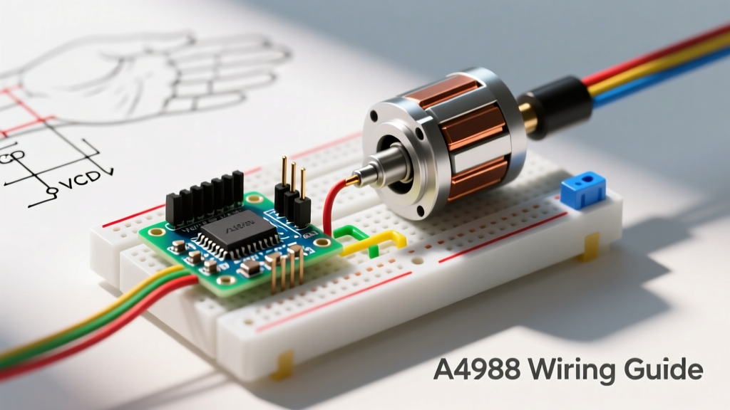
Wiring a stepper motor is not as simple as plugging in a DC brushed motor. You must correctly identify the bipolar coil pairs and separate the logic voltage from the motor voltage. Below is the definitive wiring matrix for this setup.
| A4988 Pin | Arduino Uno R4 Pin | NEMA 17 Wire | Function & Notes |
|---|---|---|---|
| STEP | D3 | - | Receives pulse signals to move one microstep |
| DIR | D4 | - | High = Clockwise, Low = Counter-Clockwise |
| 1A | - | Black (Coil A) | Motor Coil A positive |
| 1B | - | Green (Coil A) | Motor Coil A negative |
| 2A | - | Red (Coil B) | Motor Coil B positive |
| 2B | - | Blue (Coil B) | Motor Coil B negative |
| VMOT | 24V PSU (+) | - | Motor power input (8V - 35V) |
| GND | PSU GND + Arduino GND | - | Common ground (CRITICAL: Must share ground with Arduino) |
| VDD | 5V (Optional) | - | Logic power (Usually powered via internal 3.3V regulator) |
CRITICAL WARNING: Never disconnect or reconnect the NEMA 17 motor wires while the A4988 driver is powered on. The resulting voltage flyback spike will instantly destroy the driver's internal H-bridge MOSFETs, even if the motor is not actively moving.
Identifying Coil Pairs Without a Datasheet
If you bought surplus motors and the wire colors don't match the standard black/green/red/blue scheme, use a digital multimeter set to continuity or resistance mode. Measure the wires in pairs. Two wires will show a low resistance (typically 1.5 to 3.0 ohms)—this is Coil A. The other two wires will show the same resistance—this is Coil B. If you measure infinite resistance, you are testing one wire from Coil A and one from Coil B. Alternatively, short two wires together with a jumper and try to spin the motor shaft by hand. If you feel distinct magnetic cogging resistance, you have found a matching coil pair.
The Most Skipped Step: Calibrating Vref (Current Limit)
The number one reason beginners burn out their A4988 drivers or experience severe missed steps is skipping the Vref calibration. The A4988 has a small potentiometer that sets the maximum current delivered to the motor. If set too high, the driver overheats and triggers thermal shutdown. If set too low, the motor stalls under load.
To calibrate, you need to calculate the reference voltage ($V_{ref}$) using this formula:
$V_{ref} = I_{max} \times 8 \times R_{sense}$
The 2026 Resistor Gotcha: Older tutorials assume an $R_{sense}$ value of 0.1 ohms. However, almost all generic A4988 clones manufactured from 2024 onward use 0.05 ohm sense resistors to handle higher currents. Check the SMD resistor on your board; it will be stamped with 'R05' (0.05) or 'R10' (0.1).
For a standard 1.5A NEMA 17 motor using a board with a 0.05 ohm resistor:
- $V_{ref} = 1.5A \times 8 \times 0.05\Omega = 0.6V
How to measure and adjust:
- Power the Arduino and A4988 logic (via USB), but do not connect the high-voltage VMOT yet.
- Set your multimeter to DC Voltage (20V range).
- Place the black probe on the Arduino GND pin.
- Place the red probe gently on the metal shaft of the potentiometer or the TP1 test pad.
- Use a ceramic screwdriver to turn the pot clockwise to increase voltage, or counter-clockwise to decrease it until you hit exactly 0.6V.
Microstepping Configuration
Microstepping divides each full step (1.8 degrees, or 200 steps/rev) into smaller fractions, resulting in smoother motion and reduced resonance. The A4988 uses three pins (MS1, MS2, MS3) to configure this. Connect these to Arduino digital pins or hardwire them to 5V/GND.
| MS1 | MS2 | MS3 | Microstep Resolution | Steps per Revolution |
|---|---|---|---|---|
| Low | Low | Low | Full Step | 200 |
| High | Low | Low | 1/2 Step | 400 |
| Low | High | Low | 1/4 Step | 800 |
| High | High | Low | 1/8 Step | 1600 |
| High | High | High | 1/16 Step | 3200 |
Writing the Code: AccelStepper vs. Native Stepper.h
While the Arduino IDE includes a native Stepper.h library, it is fundamentally flawed for real-world physics. It commands the motor to instantly jump to a target speed, which causes massive inertia spikes, resulting in missed steps and stalled rotors. Instead, we use Mike McCauley's AccelStepper Library, which calculates trapezoidal acceleration and deceleration profiles.
Install the library via the Arduino Library Manager (search 'AccelStepper'), then upload the following robust baseline code:
#include <AccelStepper.h>

// Define the stepper and the pins it uses
// Interface type 1 = External Driver (Step/Dir)
AccelStepper stepper(AccelStepper::DRIVER, 3, 4); // STEP=3, DIR=4

const int EN_PIN = 5; // Enable pin (Active LOW)

void setup() {
  pinMode(EN_PIN, OUTPUT);
  digitalWrite(EN_PIN, LOW); // Enable the driver immediately

  // Configure AccelStepper parameters
  // Max speed in steps/sec. For 1/16 microstepping, 1600 steps = 1 rev/sec (60 RPM)
  stepper.setMaxSpeed(1600);

  // Acceleration in steps/sec^2. Start conservative to prevent stalling.
  stepper.setAcceleration(800);

  // Set current position to zero
  stepper.setCurrentPosition(0);

  // Command motor to move 3200 steps (2 full revolutions at 1/16 microstepping)
  stepper.moveTo(3200);
}

void loop() {
  // If the motor hasn't reached its target position
  if (stepper.distanceToGo() != 0) {
    stepper.run(); // Must be called as frequently as possible
  } else {
    // Optional: Disable driver when stationary to save power and reduce heat
    // digitalWrite(EN_PIN, HIGH);
  }
}
Real-World Failure Modes and Troubleshooting
Even with perfect wiring, mechanical and electrical edge cases will arise. Here is how to diagnose the most common issues encountered when integrating NEMA 17 motors into custom rigs.
1. Motor Vibrates Violently but Doesn't Rotate
Cause: The acceleration value in AccelStepper is set higher than the motor's pull-in torque can handle, or the coil pairs are wired out of phase.
Fix: Drop the acceleration value by 50% in your code. If that fails, swap the two wires of Coil A (e.g., swap Black and Green). Stepper motors require a specific electromagnetic sequencing order; reversing one coil reverses the magnetic field sequence, causing the rotor to fight itself.
2. Driver Overheats and Randomly Stops (Thermal Throttling)
Cause: The A4988 features internal thermal shutdown at approximately 165°C. Generic clone boards often lack adequate copper pours on the PCB to dissipate heat, causing the chip to throttle even at 1.0A.
Fix: According to the Pololu A4988 Stepper Motor Driver Carrier documentation, the chip can only deliver 1.0A per phase without active cooling. You must attach an aluminum heatsink and point a 40mm 5V fan directly at the driver. Alternatively, lower your Vref to limit the current to 0.8A if your mechanical load permits.
3. Severe Loss of Torque at High Speeds
Cause: NEMA 17 motors suffer from inductance limitations. As RPM increases, the current cannot build up fast enough in the coils before the next step is commanded, causing a sharp drop-off in torque above 800-1000 RPM.
Fix: Increase the VMOT voltage. Running the A4988 at 24V instead of 12V forces current through the inductive coils much faster, extending your usable torque curve significantly higher into the RPM range. Ensure your VMOT never exceeds the A4988's absolute maximum of 35V.
Frequently Asked Questions
Can I power the A4988 VMOT directly from the Arduino's 5V pin?
No. The Arduino's onboard 5V regulator is typically rated for 500mA to 1A maximum. A NEMA 17 motor under load will draw 1.5A to 3.0A (across both coils). Attempting to pull motor current through the Arduino will instantly fry the board's voltage regulator or USB trace. Always use a dedicated external buck converter or DC power supply for VMOT.
Do I need to use all three microstepping pins (MS1, MS2, MS3)?
No. If you leave the MS pins floating (unconnected), the A4988's internal pull-down resistors will default the driver to full-step mode. However, full-step mode is notoriously loud and prone to low-speed resonance. For most DIY robotics and camera sliders, hardwiring MS1, MS2, and MS3 to 5V (1/16th stepping) yields the best acoustic and mechanical performance.