
The Reality of Color Sensing in 2026: TCS3200 vs. TCS34725
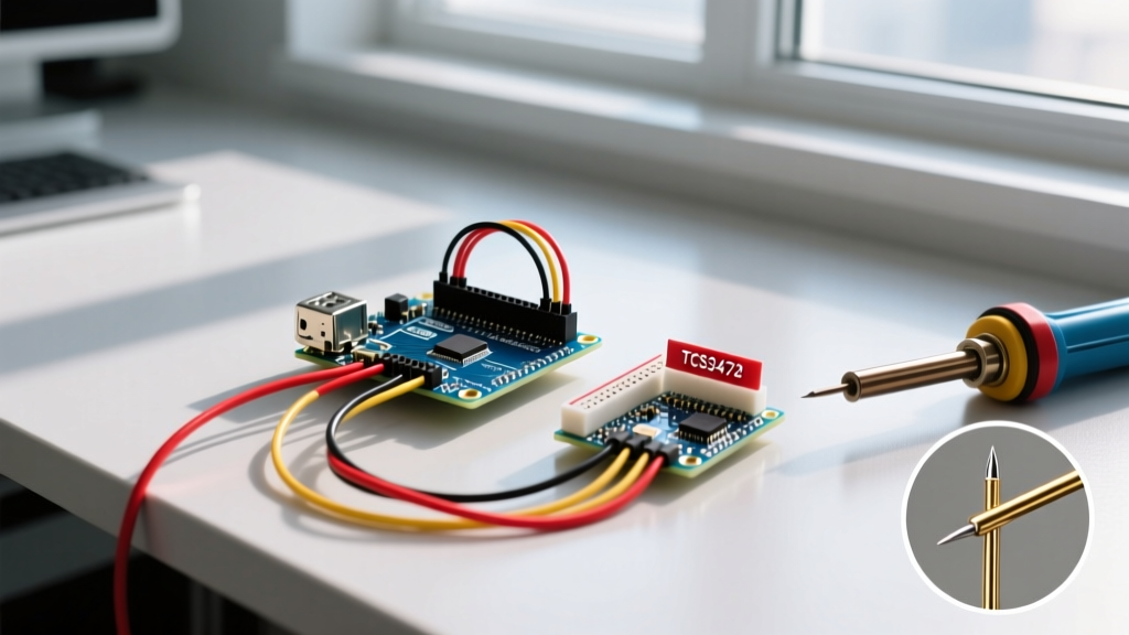
Integrating a color sensor into an Arduino project often begins with high expectations and ends in frustration when raw RGB values fluctuate wildly under different lighting conditions. As of 2026, the maker market is dominated by two primary architectures: the legacy TCS3200 (a frequency-based light-to-color converter) and the modern TCS34725 (an I2C-based RGB sensor with an integrated IR-blocking filter). While the TCS34725 has largely superseded the TCS3200 in professional prototyping due to its superior ambient light rejection, both modules present unique hardware and software failure modes.
This troubleshooting guide bypasses generic wiring diagrams and dives directly into the edge cases, I2C bus lockups, ADC saturation issues, and optical interference patterns that cause Arduino color sensor projects to fail in real-world environments.
Diagnosing I2C Bus Lockups and Address Conflicts (TCS34725)
The TCS34725 communicates via I2C at the default address 0x29. A common failure mode is the Arduino Wire library hanging indefinitely or returning 0xFFFFFFFF during initialization. This is rarely a defective sensor; it is almost always a bus topology or voltage issue.
The Pull-Up Resistor Deficit
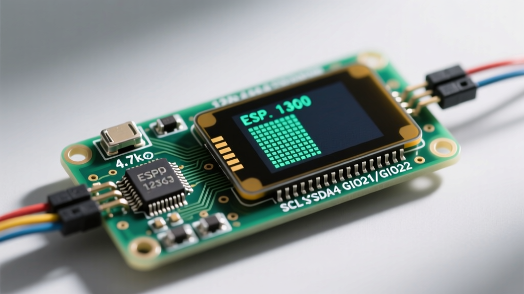
Many breakout boards include 10kΩ pull-up resistors on the SDA and SCL lines. While 10kΩ might work on a short 5cm trace, it is insufficient for reliable I2C communication at 400kHz, especially when parasitic capacitance is introduced by jumper wires. According to SparkFun's TCS34725 Hookup Guide, upgrading to 4.7kΩ or even 2.2kΩ pull-up resistors on the 3.3V line drastically reduces rise-time jitter and prevents bus lockups.
5V Logic Frying the 3.3V I2C Bus
The TCS34725 is strictly a 3.3V device. If you are using a 5V Arduino Uno or Mega, sending 5V logic directly into the SDA/SCL pins will eventually degrade the sensor's internal ESD protection diodes, leading to intermittent I2C acknowledgment failures. You must use a bi-directional logic level shifter (such as a BSS138 MOSFET-based module) to safely translate the 5V Arduino signals to 3.3V.
ADC Saturation: Fixing 65535 Max Value Errors
When your TCS34725 consistently returns 65535 (the maximum 16-bit integer value) for the Red, Green, Blue, or Clear channels, the sensor's internal ADC is saturating. This happens when the integration time is too long for the ambient light level, causing the photodiode capacitors to fully charge before the conversion cycle ends.
To resolve this, you must dynamically adjust the integration time based on the Clear (C) channel reading. Below is the hardware mapping for integration cycles and their corresponding saturation thresholds:
| Integration Time (ms) | Hex Register Value | Max Cycles | Saturation Lux (Approx) | Best Use Case |
|---|---|---|---|---|
| 2.4 ms | 0xFF | 1 | High (Direct Sunlight) | Outdoor sorting, high-brightness LEDs |
| 24 ms | 0xF6 | 10 | Medium-High | Well-lit indoor environments |
| 101 ms | 0xD5 | 42 | Medium | Standard room lighting (300-500 lux) |
| 700 ms | 0x00 | 256 | Low (Dim/Shadow) | Low-light object detection, enclosed chambers |
Actionable Fix: If you are using the Adafruit library, change your initialization from TCS34725_INTEGRATIONTIME_700MS to TCS34725_INTEGRATIONTIME_24MS when operating under standard overhead LED room lighting. For advanced implementations, write a routine that checks the Clear channel; if it exceeds 60,000, step down the integration time dynamically.
TCS3200 Frequency Scaling and PulseIn() Timeouts
The TCS3200 outputs a square wave whose frequency is directly proportional to light intensity. Arduino users typically read this using the pulseIn() function. A frequent troubleshooting scenario is pulseIn() returning 0, indicating a timeout.
The S0 and S1 Power-Down Trap
The S0 and S1 pins dictate the output frequency scaling (100%, 20%, 2%, or power-down). If both S0 and S1 are pulled LOW, the sensor enters a low-power sleep mode, and the OUT pin goes high-impedance. The Arduino will read no pulses, resulting in a timeout. Ensure your code explicitly sets S0 to HIGH and S1 to LOW (for 20% scaling, which is optimal for the 16MHz Arduino clock to avoid timer overflow).
Capacitive Loading on the OUT Pin
If your frequency readings are erratic or drifting, check the physical wiring. The TCS3200 OUT pin struggles to drive high-capacitance loads. Using long, unshielded ribbon cables introduces parasitic capacitance that rounds off the square wave edges, causing the Arduino's digital interrupt to misfire. Keep the OUT wire under 15cm, or buffer it using a 74HC14 Schmitt trigger inverter to clean up the signal edges before it reaches the microcontroller.
Optical Shrouding and Ambient Light Rejection
No amount of software calibration can fix poor optical physics. Both the TCS3200 and TCS34725 suffer from specular reflection and ambient light bleed if left exposed. As noted in Adafruit's comprehensive color sensor overview, the sensor must be isolated from the environment to ensure the only light hitting the photodiodes is the light reflecting off your target object.
- Material: 3D print a shroud using Matte Black PLA or PETG. Glossy black filament reflects IR and visible light internally, skewing the RGB ratios.
- Focal Distance: The integrated LEDs on most breakout boards are optimized for a 10mm to 15mm target distance. Mounting the sensor 30mm away will result in a weak signal-to-noise ratio; mounting it at 2mm will cause specular hotspots (saturation on a single color channel).
- LED CRI: If your breakout board uses cheap, cool-white SMD LEDs, they likely have a massive spike in the blue spectrum and a deficit in red. For high-accuracy sorting, desolder the onboard LEDs and wire in high-CRI (95+) external LEDs, or rely entirely on the TCS34725's ability to read ambient illumination in a controlled light box.
Software White-Balancing via the Clear Channel
Raw RGB values are useless for color classification because they change based on the object's distance and the ambient light intensity. To achieve reliable color detection, you must normalize the RGB values against the Clear (C) channel, which acts as a broadband luminance reference.
Normalization Formula:
R_norm = (R_raw / C_raw) * 255
G_norm = (G_raw / C_raw) * 255
B_norm = (B_raw / C_raw) * 255
By dividing the individual color channels by the Clear channel, you effectively cancel out the distance and brightness variables, leaving you with a pure chromaticity ratio. For even greater accuracy in 2026's advanced DIY applications, apply a gamma correction factor (typically 2.2) to the normalized values before mapping them to your decision matrix or machine learning classification model.
Summary of Failure Modes
Troubleshooting an Arduino color sensor requires a systematic approach. If the sensor fails to initialize, audit your I2C pull-ups and logic levels. If the values are maxed out, reduce your integration time. If the colors shift when you move the object, implement Clear-channel normalization and build a proper matte-black optical shroud. For deeper architectural data, refer to the official ams OSRAM TCS34725 datasheet to understand the exact timing diagrams and register maps governing the sensor's state machine.