
The Challenge of Multi-Peripheral Integration
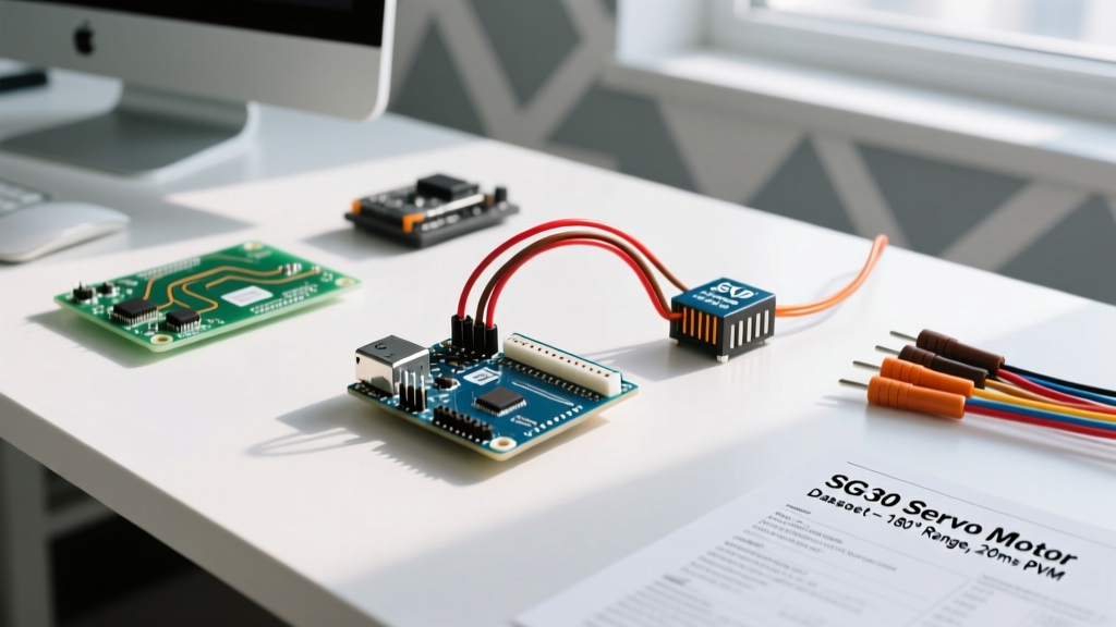
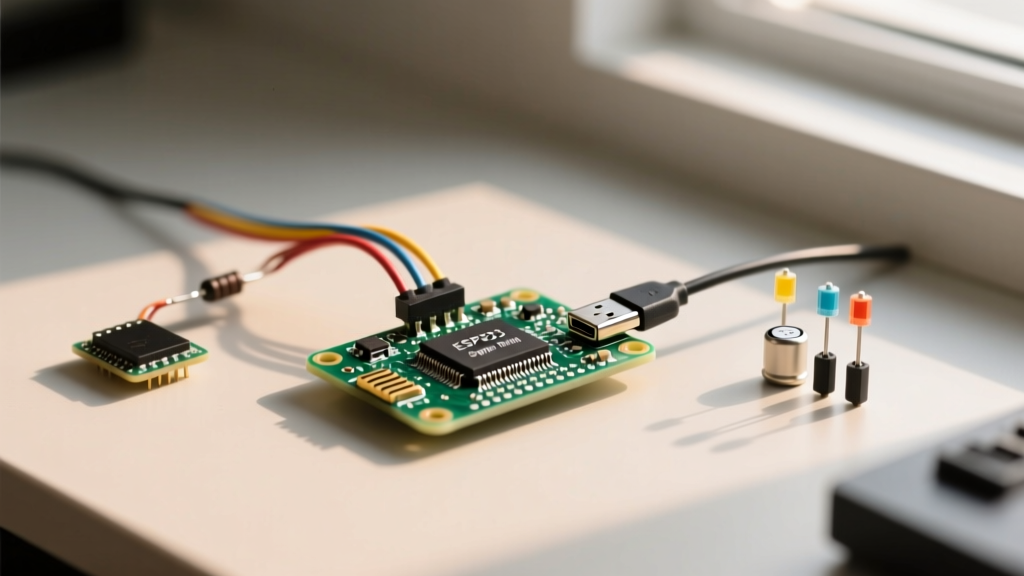
When designing a complex robotics or IoT project, relying on a single sensor is rarely enough. A typical multi-peripheral gyro sensor Arduino setup might require integrating a 6-axis IMU, an SSD1306 OLED display, a BME280 environmental sensor, and a motor driver all on the same microcontroller. While the Arduino Uno R4 Minima and Nano 33 IoT offer robust processing power, the physical limitations of the I2C and SPI buses often become the primary bottleneck.
Historically, hobbyists defaulted to the InvenSense MPU6050 for gyroscopic data. However, as of 2026, the MPU6050 is largely considered legacy hardware due to its high noise floor and discontinued status in professional supply chains. Modern multi-device setups demand higher precision and lower power consumption, shifting the standard toward sensors like the Bosch BMI270 or the TDK ICM-42688-P. Integrating these modern sensors alongside multiple peripherals requires a strict understanding of bus capacitance, logic level translation, and address collision management.
Selecting the Right Gyroscope for Multi-Device Buses
Choosing the correct module dictates your wiring topology. Below is a comparison of the most relevant gyroscopic sensors for modern Arduino multi-peripheral builds, factoring in I2C flexibility and power draw.
| Sensor Model | Default I2C Address | Logic Level | Bus Flexibility | Typical Cost (2026) |
|---|---|---|---|---|
| Bosch BMI270 | 0x68 / 0x69 | 3.3V Strict | High (Configurable FIFO) | $12.00 - $15.00 |
| TDK ICM-42688-P | 0x68 / 0x69 | 3.3V Strict | Very High (Low Noise, High ODR) | $14.00 - $18.00 |
| MPU6050 (Legacy) | 0x68 / 0x69 | 5V Tolerant (3.3V LDO) | Low (Fixed FIFO, High Noise) | $4.00 - $7.00 |
For a multi-peripheral build involving an OLED and environmental sensors, the BMI270 is highly recommended. Its advanced FIFO buffer allows the Arduino to sleep longer, reducing overall bus traffic and minimizing I2C collisions with high-priority devices like real-time clocks.
The I2C Bus Capacitance Bottleneck
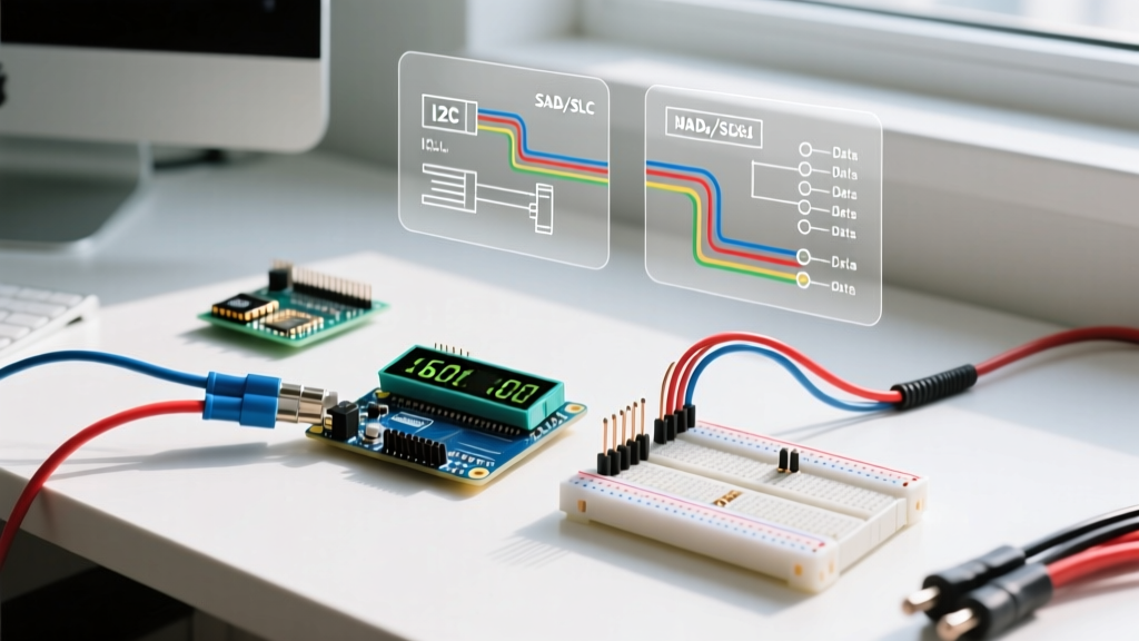
The most common point of failure in a multi-peripheral gyro sensor Arduino project is ignoring the I2C bus capacitance limit. According to the NXP I2C-bus specification (UM10204), the maximum allowable bus capacitance is 400pF. Every module, wire, and breadboard trace adds parasitic capacitance.
- Breadboard traces: ~2pF per centimeter
- Standard sensor breakout board: ~10pF to 15pF
- OLED Display module: ~20pF
- Jumper wires (Dupont): ~3pF per 10cm
If you connect a BMI270 gyro, an SSD1306 OLED, a BME280, and a DS3231 RTC, you are accumulating roughly 60pF to 80pF of device capacitance alone. While this is under the 400pF limit, adding long jumper wires or utilizing unshielded cables near brushless motor ESCs will introduce noise that mimics capacitance, degrading the square wave signal into a sawtooth wave and causing packet corruption.
Calculating Pull-Up Resistor Values
To combat capacitance, you must correctly size your I2C pull-up resistors. The Texas Instruments Application Note SLVA704 outlines that smaller resistors pull the line high faster, but draw more current. Most breakout boards include 4.7kΩ or 10kΩ pull-ups. When combining three or more boards in parallel, these resistors combine in parallel, potentially dropping the total resistance below the safe 3mA sink limit of the microcontroller.
Expert Tip: If your multi-peripheral setup includes three or more I2C modules, disable the onboard pull-up resistors on all but one module, and install a dedicated 2.2kΩ pull-up resistor pair directly on the main SDA/SCL breadboard rails for 400kHz Fast Mode operation.
SPI vs. I2C: Offloading the Gyroscope
When your gyro sensor Arduino setup requires high-frequency polling (e.g., reading 1000Hz gyro data for PID motor control while simultaneously updating a display), the I2C bus will choke. I2C is half-duplex and relatively slow. In these scenarios, moving the gyroscope to the hardware SPI bus is mandatory.
Using the Arduino Uno R4 Minima, the hardware SPI pins are D11 (MOSI), D12 (MISO), and D13 (SCK). You can wire the BMI270 to these pins and assign it a dedicated Chip Select (CS) pin, such as D10. This leaves the I2C bus (A4/A5) entirely free for the OLED, RTC, and environmental sensors, eliminating bus contention and ensuring your gyro data arrives without latency spikes.
Step-by-Step Multi-Peripheral Wiring Guide
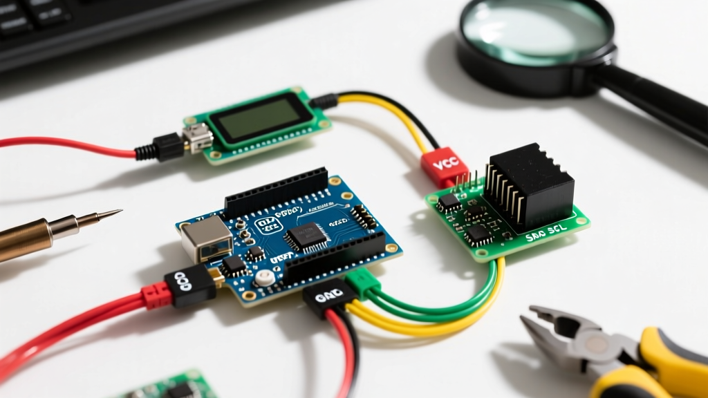
Below is the optimal wiring topology for an Arduino Uno R4 Minima utilizing a BMI270 (SPI), an SSD1306 OLED (I2C), and a BME280 (I2C).
- Power Rails: Connect the Arduino 3.3V output to the positive rail and GND to the negative rail. Never power 3.3V gyro sensors from the 5V pin, even if the breakout has an LDO; it introduces thermal noise.
- I2C Bus (OLED & BME280): Wire SDA to A4 and SCL to A5. Ensure both modules share the common 3.3V and GND rails.
- SPI Bus (BMI270 Gyro): Wire SCK to D13, MOSI to D11, MISO to D12, and CS to D10.
- Interrupt Pins: Wire the BMI270 INT1 pin to Arduino D2. This allows the gyro to trigger a hardware interrupt when the FIFO buffer is full, freeing the MCU to handle I2C display updates in the main loop.
Resolving Address Collisions with Multiplexers
What happens if your project requires two identical gyroscopes for redundant IMU tracking? Both BMI270 modules will default to I2C address 0x68. Even by toggling the SDO pin high on one module to shift it to 0x69, you cannot add a third. The solution is the TCA9548A I2C Multiplexer (typically $4.50). This chip sits on the main I2C bus and provides 8 isolated downstream channels. By sending a quick I2C command to the TCA9548A, you can route the Arduino's SDA/SCL signals to specific gyroscopes, completely bypassing address limitations and isolating bus capacitance per channel.
Real-World Failure Modes and Troubleshooting
Even with perfect wiring, multi-peripheral setups introduce unique edge cases. Here is how to diagnose and fix the most common hardware-level failures.
1. The I2C Bus Lockup
If the Arduino resets or loses power while an I2C slave (like the OLED or BME280) is actively transmitting a '0' bit, the SDA line gets stuck LOW. Upon reboot, the Arduino Wire Library will hang indefinitely on Wire.begin(). The Fix: Implement a software I2C bus recovery routine in your setup() function that manually toggles the SCL pin 9 times as a GPIO output. This forces the slave to complete its byte and release the SDA line before initializing the Wire library.
2. Logic Level Translation Mismatch
Connecting a 5V Arduino Uno R3 directly to a 3.3V BMI270 without a bidirectional logic level shifter (like the BSS138 MOSFET circuit) will slowly degrade the gyro's I/O pins. While it may work for a few days, the absolute maximum rating for the BMI270 I/O is 3.6V. Always use a dedicated bi-directional logic level shifter (costing roughly $2.00) between 5V microcontrollers and 3.3V sensor arrays.
3. Motor EMI Corrupting Gyro Data
When integrating motor drivers (like the DRV8833) into the same physical chassis, the back-EMF from brushed DC motors injects high-frequency noise into the I2C lines, causing the gyro to output NaN (Not a Number) or zeroed axes. The Fix: Route I2C/SPI wires away from motor power lines. If they must cross, cross them at a strict 90-degree angle. Additionally, solder 100nF ceramic decoupling capacitors directly across the motor terminals to suppress brush noise at the source.
Conclusion
Building a reliable multi-peripheral gyro sensor Arduino system requires moving beyond simple plug-and-play tutorials. By respecting the 400pF I2C capacitance limit, correctly sizing pull-up resistors, offloading high-speed IMUs to the SPI bus, and implementing hardware bus recovery protocols, you ensure your sensor array operates flawlessly in real-world conditions. Upgrading from legacy modules to modern sensors like the BMI270 not only improves data fidelity but drastically reduces the power and bus overhead of your entire embedded system.