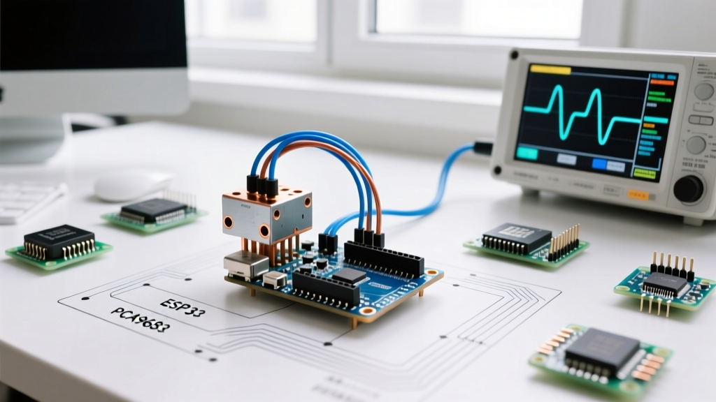

Beyond the Basic Sweep: Engineering a Reliable Servo Test
When makers first learn to servo test Arduino setups, they typically upload the default 'Sweep' example and watch a micro servo twitch back and forth. While this confirms basic connectivity, it completely ignores the electrical and programmatic realities of deploying servos in real-world robotics, camera gimbals, or automated actuators. A true servo test requires evaluating torque under load, eliminating PWM jitter, managing power rail brownouts, and selecting the correct driver library for your specific kinematic requirements.
In this comprehensive library and driver guide, we dissect the software stacks and hardware configurations necessary to execute a professional-grade servo test using Arduino microcontrollers in 2026. Whether you are driving a $3 TowerPro SG90 or a $25 Hiwonder DS3218 20kg high-torque servo, the principles of pulse-width modulation (PWM) timing and power decoupling remain critical.
Hardware Prerequisites: Matching Servos to Power and Drivers
Before writing a single line of C++, you must match your servo's electrical characteristics to an appropriate power supply. The most common point of failure during an Arduino servo test is attempting to draw high stall current through the Arduino's onboard 5V linear regulator, which typically maxes out at 500mA to 800mA and will trigger a thermal shutdown or permanently damage the board's polyfuse.
| Servo Model | Operating Voltage | Stall Torque (at 6V) | Stall Current Draw | Recommended Driver / Power Setup |
|---|---|---|---|---|
| TowerPro SG90 (9g) | 4.8V - 6.0V | 1.8 kg-cm | ~650mA | Arduino 5V pin (1 servo max) or USB |
| TowerPro MG996R | 4.8V - 7.2V | 13 kg-cm | ~2.5A | External 5V/6V 3A BEC or Buck Converter |
| Hiwonder DS3218 | 4.8V - 8.4V | 20 kg-cm | ~3.2A | External 6V 5A Power Supply + PCA9685 |
| Feetech SCS15 (Serial) | 6.0V - 12.0V | 15 kg-cm | ~2.0A | UART Serial Bus (Not PWM) |
Pro-Tip for Power Decoupling: Always place a 470µF to 1000µF electrolytic capacitor across the VCC and GND rails of your external servo power supply. This absorbs the sudden current spikes generated when the servo motor starts moving, preventing voltage sags that cause the Arduino to brownout and reset mid-test.
Core Libraries for Arduino Servo Testing
The software layer dictates how precisely you can control the servo's internal potentiometer feedback loop. Here is a breakdown of the three primary libraries used for PWM servo control, ranging from basic to advanced.
1. The Built-in Servo.h (Baseline Testing)
The native Arduino Servo Library is pre-installed in the Arduino IDE. It generates a 50Hz PWM signal (a pulse every 20ms) using the microcontroller's hardware timers. By default, the write(angle) function maps 0-180 degrees to a pulse width of 544 to 2400 microseconds.
The Catch: On ATmega328P-based boards (Uno, Nano), Servo.h hijacks Timer1. This disables standard analogWrite() PWM functionality on pins 9 and 10. If your test rig requires simultaneous DC motor speed control via those pins, you will encounter silent failures. Furthermore, Servo.h updates the pulse instantaneously, which can cause violent mechanical jerking if the servo is under heavy load.
2. VarSpeedServo for Controlled Acceleration
When testing camera pan/tilt mechanisms or delicate robotic grippers, instantaneous movement is unacceptable. The VarSpeedServo library extends the standard API by introducing the slowmove(angle, speed) method. This allows you to dictate the transition speed (from 1 to 255) without requiring complex for loops and delay() functions that block the Arduino's main execution thread. It is ideal for testing the mechanical limits of gears under controlled acceleration profiles.
3. Adafruit PWM Servo Driver (PCA9685) for I2C Offloading
For multi-servo arrays (like hexapod legs or robotic arms), relying on the Arduino's internal timers is a recipe for jitter and pin exhaustion. The NXP PCA9685 chip, commonly found on Adafruit 16-Channel PWM/Servo Shields and cheap $3 clone breakout boards, handles PWM generation entirely over I2C.
According to the NXP PCA9685 Datasheet, the chip offers 12-bit resolution (4096 steps) per channel. Because the PCA9685 has its own dedicated oscillator, the PWM signal remains perfectly stable even if the Arduino is busy processing complex inverse kinematics or sensor fusion algorithms. This is the gold standard for professional servo testing.
Step-by-Step: Executing a Jitter-Free Servo Test
To perform a definitive servo test that evaluates both range of motion and holding torque, follow this structured workflow using the PCA9685 driver and an external power supply.
- Establish Common Ground: Connect the GND of the Arduino, the GND of the PCA9685 breakout board, and the GND of the external 5V/6V power supply together. A missing common ground is the #1 cause of erratic servo jitter.
- Wire the I2C Bus: Connect SDA to A4 and SCL to A5 on an Arduino Uno/Nano (or pins 20/21 on a Mega).
- Set the I2C Address: If using multiple PCA9685 boards, solder the address jumpers (A0-A5) on the back of the PCB. The default address is 0x40.
- Calibrate Microsecond Limits: Do not rely on the default 0-180 degree mapping. Use the
setPWM()function to manually send pulse widths starting at 1000µs and incrementing by 10µs. Note the exact microsecond values where the servo physically stops moving at both extremes. This prevents the servo from continuously stalling and drawing maximum current against its internal hard stops. - Load Testing: Attach the anticipated mechanical load. Command the servo to hold a 90-degree position. Use a multimeter with a current clamp to measure the holding current. If it exceeds the manufacturer's continuous rating, you must upgrade the servo or add mechanical gearing.
Troubleshooting Common Servo Test Failures
Even with perfect code, electrical noise and mechanical binding can ruin a servo test. Here is how to diagnose the most frequent edge cases:
- Micro-Jitter at Rest: If the servo vibrates slightly when holding a position, you likely have a ground loop or noisy power supply. Switch to a linear power supply instead of a cheap switching buck converter, or add a 0.1µF ceramic capacitor directly across the servo's VCC and GND pins at the connector.
- Arduino Brownout Resets: If the Arduino restarts when the servo begins moving, the servo's startup current spike is pulling the shared USB voltage below 4.5V. Isolate the servo power entirely from the Arduino's USB line, relying only on the common ground and the PWM signal wire.
- Positional Drift: If the servo slowly creeps away from the commanded angle over time, the internal potentiometer may be dirty or the feedback loop gain is mismatched to the load. In high-vibration environments, consider upgrading to a digital servo (like the DS3218) which samples the potentiometer at 330Hz compared to the 50Hz of analog servos.
- Stripped Gears on MG996R: The MG996R is notorious for having soft aluminum top gears. If your test involves sudden directional reversals under load, the inertia will strip the gears. Implement software acceleration ramping or switch to steel-gear variants like the MG995.
Calculating 12-Bit PWM Values for the PCA9685
When using the PCA9685 library, you don't pass microseconds directly; you pass 12-bit integer values (0 to 4095). To translate your desired microsecond pulse width into a PCA9685 tick value, use the following formula based on a standard 50Hz (20ms) frequency:
Tick Value = (Desired Microseconds / 20,000) * 4096
For example, a standard 1.5ms (1500µs) center pulse translates to:
(1500 / 20000) * 4096 = 307.2 (Round to 307).
Understanding this math is crucial when you need sub-degree precision for applications like LiDAR scanning or optical alignment rigs.
Summary
Executing a proper servo test Arduino project requires moving past basic tutorials. By matching your servo's stall current to an external BEC, decoupling your power rails, and leveraging advanced libraries like VarSpeedServo or I2C offloading via the PCA9685, you ensure mechanical longevity and signal integrity. Always calibrate your microsecond limits manually to protect both your hardware and your power supply.