
The I/O Bottleneck: Why Parallel LCDs Fail in Complex Arrays
When designing multi-sensor environmental monitors or robotics dashboards, microcontroller I/O pins are a finite resource. A standard parallel 16x2 display consumes up to six digital pins, leaving insufficient headroom for integrating an arduino lcd screen alongside critical peripherals like a BME280 environmental sensor, a PIR motion detector, and a stepper motor driver. In 2026, the industry standard for multi-peripheral setups has decisively shifted toward I2C-enabled displays using backpack modules. This architecture reduces the display footprint to just two shared bus pins (SDA and SCL), allowing you to daisy-chain dozens of sensors on the same hardware bus.
However, simply plugging an I2C LCD into a crowded bus often leads to corrupted text, flickering, or complete bus lockups. This guide details the exact electrical requirements, address conflict resolutions, and non-blocking software architectures required to reliably run an Arduino LCD screen in a dense multi-peripheral environment.
Display Module Selection for Sensor Arrays
Not all LCD modules are created equal when sharing a bus with high-frequency sensors. Below is a comparison of the most common display technologies used in complex Arduino setups, factoring in 2026 market pricing and bus impact.
| Display Type | Controller / Interface | Pins Required | Bus Impact | Avg. Cost (2026) |
|---|---|---|---|---|
| 16x2 Parallel | HD44780 / 4-bit Parallel | 6 Digital I/O | None (Direct I/O) | $2.50 - $3.50 |
| 16x2 I2C Backpack | PCF8574 + HD44780 | 2 (SDA/SCL) | Low (400kHz max) | $3.50 - $4.50 |
| 20x4 I2C Backpack | PCF8574 + HD44780 | 2 (SDA/SCL) | Low (More I2C bytes) | $5.50 - $7.00 |
| 1.44" TFT Color | ST7735S / SPI | 5 (SPI + DC/CS) | High (SPI bus load) | $8.00 - $11.00 |
For pure data-logging setups where sensor polling speed is paramount, the 16x2 or 20x4 I2C Backpack is the optimal choice. It offloads the pin-count burden to the I2C bus, which operates independently of the SPI bus used by high-speed peripherals like SD card modules or TFT screens.
Resolving I2C Address Collisions
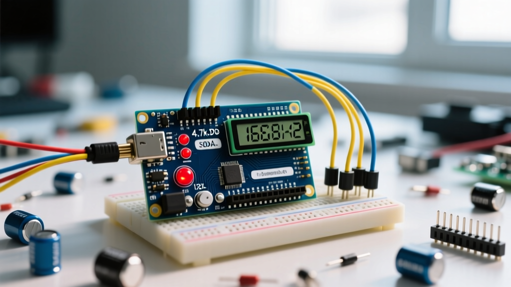
The most frequent failure point when adding an Arduino LCD screen to an existing sensor array is an I2C address collision. Most generic I2C LCD backpacks utilize the PCF8574 or PCF8574A I/O expander chips.
Critical Address Warning: The PCF8574T chip defaults to the I2C address
0x27. The PCF8574AT chip defaults to0x3F. If your LCD shares the0x27address with another peripheral (like certain relay modules or IO expanders), the microcontroller will fail to initialize both devices.
Before finalizing your wiring, always run an I2C bus scan. According to the Adafruit I2C Address Guide, maintaining a spreadsheet of your bus topology is mandatory for setups exceeding three devices. If a collision occurs, you can alter the LCD backpack address by soldering the A0, A1, and A2 jumper pads on the PCF8574 board, shifting the address sequentially up to 0x20.
Managing I2C Bus Capacitance and Pull-Up Resistors
This is where most multi-peripheral tutorials fail. The I2C specification, as documented in the NXP UM10204 I2C-bus specification, strictly limits total bus capacitance to 400pF for standard 400kHz operation. Every wire, sensor breakout board, and the LCD backpack itself adds parasitic capacitance to the SDA and SCL lines.
The Capacitance Math
- Standard 20cm Dupont wire: ~15pF per line
- BME280 Breakout Board: ~10pF
- PCF8574 LCD Backpack: ~20pF
- Arduino Uno R4 Minima internal capacitance: ~15pF
If you are running an Arduino LCD screen alongside three sensors using standard jumper wires, you can easily approach or exceed the 400pF limit, resulting in rounded signal edges and corrupted text on the display. To counteract this, you must adjust your pull-up resistors.
| Total Bus Capacitance | Required Pull-Up Resistor | Signal Rise Time Impact |
|---|---|---|
| < 200pF | 4.7kΩ | Standard (Safe for most modules) |
| 200pF - 350pF | 2.2kΩ | Faster rise time, compensates for capacitance |
| > 350pF | 1.0kΩ or Active Pull-Up | Required to prevent data corruption |
Most LCD backpacks come with a 10kΩ or 4.7kΩ pull-up resistor pre-soldered. If your bus is heavily loaded, desolder the backpack's onboard resistor and install 2.2kΩ pull-ups directly at the master microcontroller's SDA/SCL pins to ensure clean logic transitions.
Wiring the Multi-Peripheral Bus
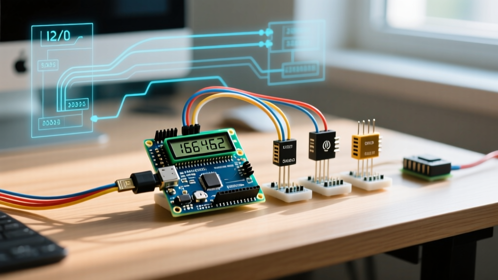
When integrating the Arduino LCD screen with sensors like the SCD40 (CO2) and SHT40 (Temp/Humidity), wire all SDA lines to a common I2C bus node and all SCL lines to a second common node. Do not use long, parallel ribbon cables for I2C, as the capacitive crosstalk between adjacent SDA and SCL wires will induce noise. Instead, use twisted-pair wiring or a dedicated I2C bus breakout board with integrated terminal blocks.
- Connect VCC (5V) and GND to the LCD and all 5V-tolerant sensors. Note: If using an ESP32-S3 (3.3V logic), ensure your LCD backpack has an onboard 3.3V regulator or use a logic level shifter.
- Route SDA to the master SDA pin (e.g., A4 on Uno R3, Pin 20 on Mega2560, or GPIO 21 on ESP32).
- Route SCL to the master SCL pin.
- Install 2.2kΩ pull-up resistors between the 5V/3.3V VCC rail and both the SDA and SCL lines.
Software Architecture: Non-Blocking Display Updates
The standard LiquidCrystal_I2C library utilizes blocking I2C transmission commands. If you use delay() or synchronous bus writes to update the Arduino LCD screen while simultaneously polling a PIR sensor or reading a fast-changing analog signal, your system will experience latency spikes. According to the Arduino Wire Library Documentation, I2C transactions can take several milliseconds, which is an eternity in a multi-sensor control loop.
Implementing a Millis-Based State Machine
To maintain high-frequency sensor polling, decouple the display update rate from the sensor read rate. Human eyes cannot perceive LCD text changes faster than 4Hz. Implement a non-blocking timer using millis() to update the screen only every 250ms, while sensors are polled every 10ms.
unsigned long lastDisplayUpdate = 0;
const long displayInterval = 250; // Update LCD at 4Hz

void loop() {
  readAllSensors(); // Runs every loop iteration (non-blocking)

  if (millis() - lastDisplayUpdate >= displayInterval) {
    lastDisplayUpdate = millis();
    updateLCDScreen(); // Only blocks the bus 4 times per second
  }
}
This architecture ensures that time-critical peripherals, such as stepper motor step-pulse generation or PID control loops, are never stalled by the relatively slow I2C write operations required to push ASCII characters to the HD44780 controller.
Troubleshooting Common Multi-Device Failures
When your Arduino LCD screen behaves erratically in a multi-peripheral setup, use this diagnostic matrix to isolate the fault.
| Symptom | Probable Cause | Hardware / Software Fix |
|---|---|---|
| Screen displays solid white boxes on the top row | I2C initialization failed; bus locked or wrong address. | Run i2cdetect; check for address collision; verify 5V logic levels. |
| Random garbage characters appearing during sensor reads | Bus capacitance exceeding 400pF; voltage sag on 5V rail. | Lower pull-up resistors to 2.2kΩ; add a 100μF decoupling capacitor at the LCD VCC/GND pins. |
| LCD backlight flickers when relay triggers | Backlight current draw causing micro-brownouts on the I2C expander. | Drive the LCD backlight LED pin via a separate MOSFET rather than sourcing current directly from the PCF8574 chip. |
| Sensors read 'NaN' when LCD is printing | Wire library buffer overflow or missing pull-ups. | Increase I2C buffer size in Wire.h; verify physical pull-up resistors are present. |
Final Integration Checklist
Before deploying your multi-sensor node, verify the following: confirm all I2C addresses are unique, measure the physical pull-up resistance on the SDA/SCL lines with a multimeter (power off) to ensure it reads between 2.2kΩ and 4.7kΩ, and ensure your code utilizes a millis() based state machine for display rendering. By respecting the electrical limits of the I2C bus and structuring your firmware for asynchronous execution, your Arduino LCD screen will serve as a reliable, real-time dashboard for even the most complex peripheral arrays.