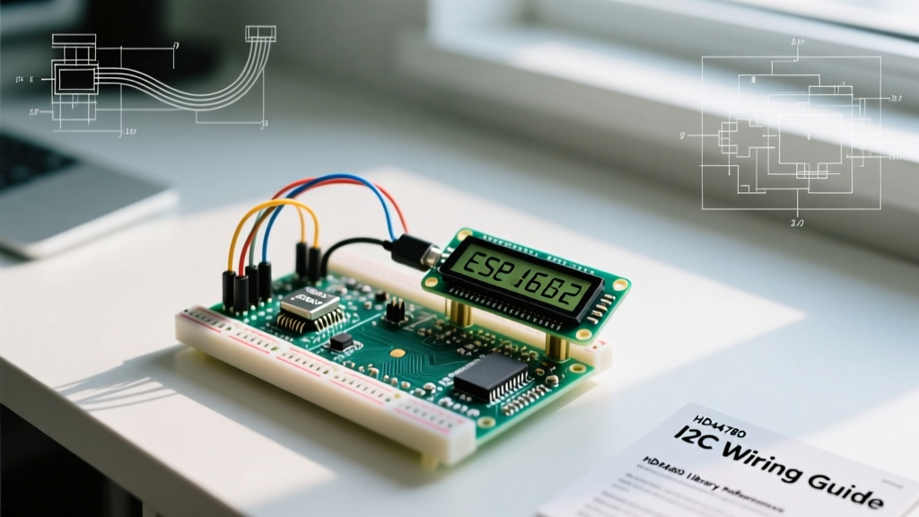

The Anatomy of an SSD1306 Display I2C OLED Module
When building a standalone environmental monitor or a custom telemetry dashboard, routing sensor data to a local screen is essential for field diagnostics. The ubiquitous 0.96-inch 128x64 display I2C OLED module, driven by the Solomon Systech SSD1306 controller, remains the gold standard for DIY sensor integration. Unlike LCDs that require backlighting and bulky potentiometers for contrast adjustment, OLED pixels emit their own light, yielding infinite contrast ratios and wide viewing angles while consuming less than 20mA during active rendering.
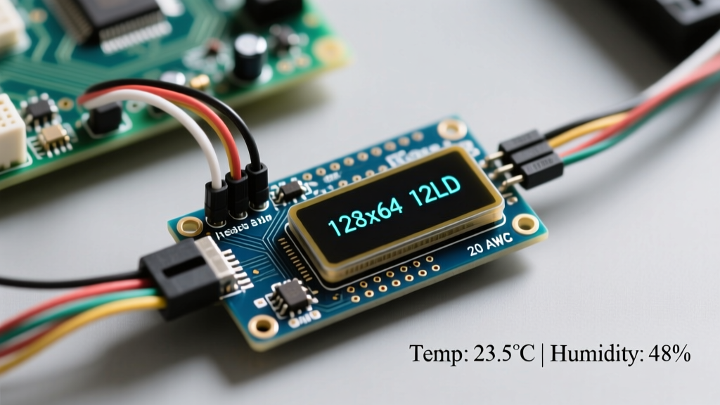
Before wiring up your microcontroller, it is critical to inspect the back of the PCB. Most generic display I2C OLED boards feature a 4-pin header (GND, VCC, SCL, SDA) and a small solder pad labeled SA0 or I2C ADDR. By default, this pad ties the address select pin to ground, locking the I2C address to 0x3C. If your sensor hub requires a second OLED, or if an address conflict arises with another peripheral, you can bridge this pad to VCC to shift the address to 0x3D. Note that cheaper 1.3-inch variants often use the SH1106 chipset, which requires a different initialization sequence and does not support hardware vertical scrolling.
Hardware Wiring: Microcontroller to Display I2C OLED
Interfacing the display I2C OLED with your microcontroller requires mapping the Serial Data (SDA) and Serial Clock (SCL) lines to the correct hardware I2C pins. While software I2C (bit-banging) is possible, hardware I2C is mandatory for stable sensor polling at 400kHz Fast Mode.
| Microcontroller | SDA Pin | SCL Pin | Logic Level | OLED VCC |
|---|---|---|---|---|
| Arduino Uno / Nano (ATmega328P) | A4 | A5 | 5V | 5V |
| ESP32 DevKit V1 | GPIO 21 | GPIO 22 | 3.3V | 3.3V |
| Raspberry Pi Pico (RP2040) | GP4 (I2C0) | GP5 (I2C0) | 3.3V | 3.3V |
Pull-Up Resistor Pitfalls and I2C Bus Capacitance
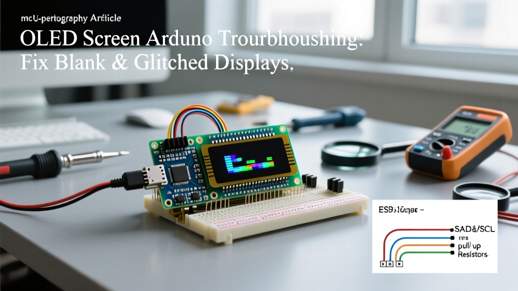
A frequent point of failure in sensor integration tutorials is the omission of I2C pull-up resistors. The I2C bus uses open-drain architecture; without pull-ups, the SDA and SCL lines will float, resulting in random noise or complete bus lockups. According to the official NXP I2C-bus specification, the bus capacitance must not exceed 400pF at 400kHz. Standard display I2C OLED modules often include 10kΩ surface-mount pull-ups on the PCB. However, when you daisy-chain multiple sensors (like a BME280 and an SCD40) alongside the OLED, the trace capacitance increases. If you experience intermittent data dropouts or ghosting on the OLED, replace the onboard 10kΩ resistors with stronger 4.7kΩ or even 2.2kΩ external pull-ups tied to VCC to sharpen the signal rise times.
Sensor Multiplexing: Sharing the I2C Bus
Integrating a display I2C OLED usually means sharing the I2C bus with the very sensors you are trying to visualize. For example, pairing the OLED (0x3C) with a Bosch BME280 temperature and humidity sensor (0x76) works seamlessly because their addresses do not overlap. However, if you attempt to integrate an AHT20 sensor alongside certain RTC modules, you may hit an address collision at 0x38.
To resolve I2C address collisions without adding a hardware multiplexer (like the TCA9548A), check your sensor's datasheet for alternative address pins. If a software workaround is impossible, utilizing a secondary software I2C bus on the ESP32 or RP2040 specifically for the OLED isolates the display traffic from high-priority sensor interrupts, ensuring your telemetry readings are never delayed by screen refresh cycles.
Firmware Strategies: Adafruit vs. U8g2 Memory Footprints
Rendering sensor data on a 128x64 pixel grid requires a framebuffer. A full-screen monochrome buffer consumes 1024 bytes of SRAM (128 * 64 / 8). When programming an 8-bit Arduino Nano with only 2KB of total SRAM, allocating 1KB just for the display I2C OLED leaves insufficient memory for sensor libraries, string formatting, and WiFi stacks.
Here is a decision framework for library selection based on your silicon:
- Adafruit_SSD1306: Excellent for ESP32, RP2040, and STM32 boards with abundant RAM. It features a familiar GFX drawing API and supports hardware scrolling. However, it strictly requires the full 1KB framebuffer in RAM.
- U8g2 (by olikraus): The undisputed champion for memory-constrained MCUs. As detailed in the U8g2 Library Wiki, it offers a 'Page Buffer' mode that renders the screen in 8-pixel high horizontal stripes. This reduces the SRAM requirement from 1024 bytes to just 128 bytes, allowing complex sensor dashboards to run flawlessly on an ATmega328P.
Code Implementation: Rendering Telemetry Without Flicker
When displaying rapidly updating sensor data (such as a barometric pressure graph or a live current draw meter), clearing the screen and redrawing causes severe flicker. To achieve a professional UI on your display I2C OLED, use selective bounding-box redraws. Instead of calling display.clearDisplay() globally, draw a filled black rectangle strictly over the numerical value area before printing the new sensor string. This localized overwrite eliminates bus redundancy and maintains a stable 60FPS visual update rate without taxing the I2C bus bandwidth.
Real-World Troubleshooting and Failure Modes
Even with perfect wiring, field deployments of I2C OLED sensor hubs encounter specific hardware anomalies. Below is a diagnostic matrix for the most common failure modes:
- The 'White Screen of Death': The display powers on and fills with solid white or random static blocks. This indicates the OLED controller is receiving power but failing to initialize via I2C. Fix: Verify your pull-up resistors and ensure the I2C clock speed is not exceeding the display's 400kHz limit. Lower the bus speed to 100kHz in your Wire library initialization.
- Sensor Data Halts When Screen Updates: The microcontroller freezes or the sensor returns NaN values precisely when the OLED renders. Fix: This is a classic I2C bus capacitance issue or a voltage brownout. The OLED can draw up to 30mA when rendering a fully white screen. If powered from a weak 3.3V LDO, the voltage droop resets the I2C peripheral. Add a 100µF decoupling capacitor directly across the OLED VCC and GND pins.
- Top Row Missing on 0.96-inch Displays: The UI renders correctly but is shifted down by two pixels, cutting off the top text. Fix: You have a clone display with a slightly different controller mapping. In the Adafruit library, change the initialization offset in the
ssd1306_command(SSD1306_SETDISPLAYOFFSET)function, or switch to the U8g2 library which auto-detects most clone variants.
Expert Integration Tip: Never connect a 5V Arduino Uno directly to the SDA/SCL pins of a 3.3V display I2C OLED without a logic level shifter (like the BSS138). While some modules feature onboard 5V tolerant LDOs, the I2C pins route directly to the silicon. Prolonged exposure to 5V logic will degrade the SSD1306 I/O diodes, leading to permanent I2C bus lockups and eventual display failure. Always use a bidirectional logic level converter for mixed-voltage sensor hubs.
By mastering the electrical nuances of the I2C bus and selecting the correct memory-management library, your display I2C OLED will transition from a fragile prototype component into a robust, field-ready telemetry interface. For further reading on optimizing sensor polling loops alongside I2C displays, consult the Adafruit OLED Breakout Wiring Guide for foundational schematic references.