
The Multi-Peripheral Bottleneck: Why Simple Wiring Fails
Integrating an infrared proximity sensor Arduino project is a foundational skill in embedded systems, but the challenge scales exponentially when you introduce secondary peripherals. In a vacuum, wiring a Sharp GP2Y0A21YK0F IR sensor to an analog pin and reading the voltage via the Arduino analogRead() Reference is trivial. However, in a 2026 multi-peripheral rig—where that same microcontroller is simultaneously driving an SSD1306 OLED display over I2C and actuating an SG90 servo via PWM—simple breadboard wiring inevitably fails.
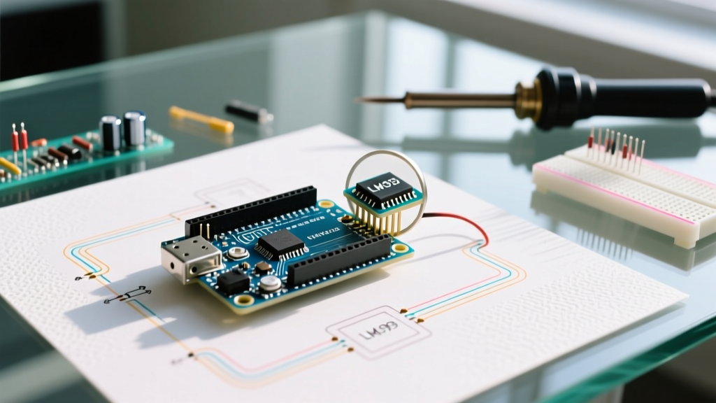
The root cause is electrical noise and power starvation. Servos induce massive back-EMF spikes and draw stall currents that collapse the 5V rail, corrupting the delicate analog-to-digital conversion (ADC) required by the IR sensor. Meanwhile, I2C bus capacitance from long jumper wires can cause OLED display flickering. This guide provides a professional-grade blueprint for building a robust, noise-isolated multi-peripheral setup using the modern Arduino Uno R4 Minima.
2026 Hardware BOM and Pinout Matrix
To achieve reliable sensor fusion, we must select components that operate harmoniously within the Uno R4's 5V logic and 3.3V internal architecture. Below is the verified Bill of Materials and routing matrix for this build.
| Component | Specific Model | Interface | Arduino Pin | Est. Cost (2026) |
|---|---|---|---|---|
| Microcontroller | Arduino Uno R4 Minima | N/A | N/A | $20.00 |
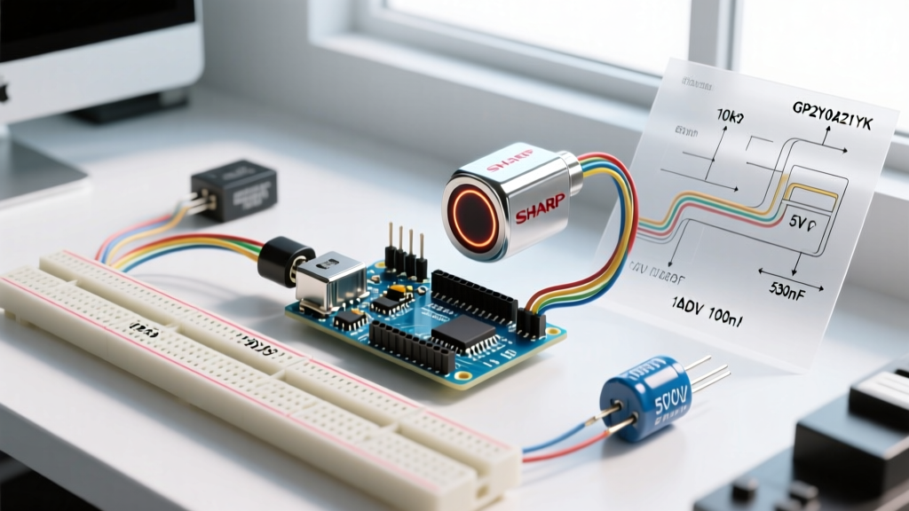
| IR Proximity Sensor | Sharp GP2Y0A21YK0F (10-80cm) | Analog | A0 | $14.99 |
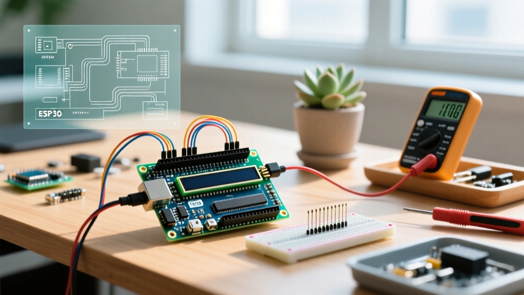
| OLED Display | Adafruit 128x64 SSD1306 | I2C | SDA/SCL | $19.95 |
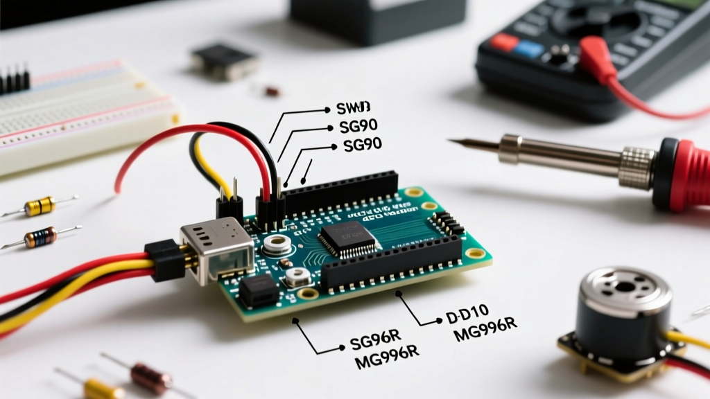
| Actuator | Tower Pro SG90 Micro Servo | PWM | D9 | $5.50 |
| Power Regulator | Pololu 5V, 9A Step-Down (D24V90F5) | Power | VIN/5V Rail | $14.95 |
Power Budgeting and ADC Noise Isolation
The most common failure mode in multi-peripheral setups is relying on the Arduino's onboard linear voltage regulator. The Uno R4's USB power path is typically limited to 500mA-1000mA. An SG90 servo can draw up to 650mA during a stall condition, while the Pololu Sharp GP2Y0A21YK0F Carrier Board draws a continuous 30mA, and the OLED draws 20mA. Pushing 700mA+ through the board's traces causes voltage sag, dropping the ADC reference voltage and resulting in erratic proximity readings.
Expert Rule of Thumb: Never share a 5V power rail between high-current inductive loads (servos, relays) and sensitive analog sensors without localized decoupling.
The Decoupling Strategy
To protect the IR sensor's ADC readings from servo-induced noise, you must implement a localized RC filter directly at the sensor's power pins. According to the Components101 GP2Y0A21YK0F Datasheet & Specs, the sensor outputs an analog voltage inversely proportional to distance. Noise on the VCC line directly modulates this output.
- Bulk Capacitor: Solder a 10µF electrolytic capacitor across the VCC and GND pins of the IR sensor to handle low-frequency voltage sags.
- High-Frequency Bypass: Place a 0.1µF (100nF) ceramic capacitor in parallel with the 10µF capacitor to shunt high-frequency PWM switching noise generated by the servo.
- Signal Filtering: Add a 10kΩ resistor in series with the analog signal wire, followed by a 0.1µF capacitor to ground at the Arduino A0 pin. This creates a low-pass RC filter with a cutoff frequency of ~159Hz, effectively eliminating high-frequency EMI.
Step-by-Step Circuit Assembly
Follow this precise assembly order to ensure ground loops do not form, which is a critical step often missed in beginner tutorials.
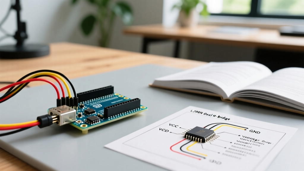
- Establish the External Power Bus: Wire the external 5V UBEC (step-down regulator) to a dedicated breadboard power rail. Connect the UBEC's ground to the Arduino's GND pin. Crucial: The ground reference must be shared, otherwise the analog signal has no return path.
- Wire the Servo: Connect the SG90 servo's red (VCC) and brown (GND) wires directly to the external 5V breadboard rail, bypassing the Arduino's 5V pin entirely. Connect the orange PWM wire to Arduino D9.
- Route the I2C OLED: Connect the SSD1306 VCC to the Arduino's 5V pin (it draws negligible current). Connect SDA to A4 and SCL to A5 (or the dedicated I2C headers on the R4). Add 4.7kΩ pull-up resistors to SDA and SCL if your OLED module lacks them onboard.
- Install the IR Sensor: Power the Sharp sensor from the external 5V rail to leverage the clean UBEC power. Connect the analog signal wire to A0 through the 10kΩ series resistor described above.
Firmware: 14-Bit ADC Oversampling
Why Standard analogRead() Fails in Multi-Peripheral Rigs
The Arduino Uno R4 features a 14-bit ADC, a massive upgrade from the 10-bit ADC on the legacy Uno R3. However, a standard analogRead() takes a single snapshot. If that snapshot coincides with a servo commutation spike, your proximity calculation will register a false obstacle.
To solve this, we implement a software-based oversampling and median filtering algorithm. Instead of taking one reading, we take 16 rapid readings, discard the highest and lowest 3 outliers (which represent noise spikes), and average the remainder.
- Sampling Rate: Set the ADC prescaler to allow ~10kHz sampling.
- Non-Blocking Execution: Use
millis()to trigger the sensor polling every 50ms. Never usedelay(), as blocking the main loop will cause the I2C OLED to stutter and the servo PWM to jitter. - Distance Mapping: The GP2Y0A21YK0F outputs a non-linear voltage curve. Do not use the
map()function. Instead, implement a lookup table (LUT) or the Steinhart-Hart-style inverse polynomial equation:Distance = (12343.85 * pow(Voltage, -1.15))for accurate centimeter calculations.
Environmental Edge Cases: Sunlight and Crosstalk
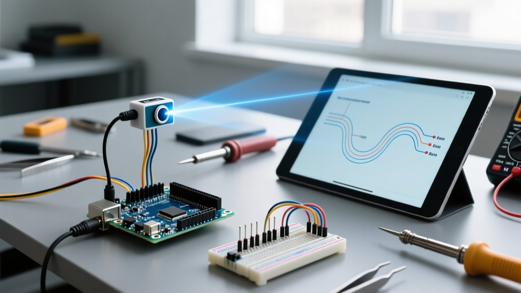
Deploying an infrared proximity sensor in real-world environments introduces optical noise. The Sharp sensor operates at an 850nm IR wavelength. Direct sunlight contains massive amounts of 850nm radiation, which can saturate the sensor's photodiode, causing it to read maximum proximity (0cm) even when the path is clear.
Mitigation Techniques
If your multi-peripheral rig is destined for outdoor or near-window use, you must implement an optical bandpass filter. A cheap, highly effective hack is to use a piece of developed, unexposed photographic film (which blocks visible light but passes IR) or a dedicated 850nm IR pass filter lens over the sensor receiver. Furthermore, if your setup utilizes multiple IR sensors, physical crosstalk will occur. Angle the sensors at least 15 degrees apart and stagger their physical height by 2cm to prevent the emitter of Sensor A from reflecting off a target into the receiver of Sensor B.
Frequently Asked Questions
Can I use a 3.3V IR sensor like the VL53L1X instead?
Yes, Time-of-Flight (ToF) sensors like the VL53L1X use I2C and are immune to analog noise and sunlight saturation. However, they require an I2C multiplexer (like the TCA9548A) if you are already using an I2C OLED, to prevent address collisions and bus capacitance issues. The analog Sharp sensor remains superior for simple, high-speed, single-target edge detection where I2C bus overhead is undesirable.
Why is my OLED flickering when the servo moves?
This is caused by I2C bus voltage droop. The servo's current draw is pulling the 5V rail down to 4.2V momentarily. The SSD1306 OLED requires a stable 3.3V logic high to recognize I2C ACK signals. When the 5V rail sags, the logic high threshold drops, corrupting the I2C packet. Using the isolated external UBEC power supply for the servo resolves this 100% of the time.
What wire gauge should I use for the servo power?
Do not use standard 22 AWG breadboard jumper wires for the servo's power and ground. The resistance of thin breadboard wires will cause a voltage drop. Use at least 18 AWG silicone wire for the servo's VCC and GND connections directly to the external power terminal block.