
Decoding the 'Arduino Move Sensor' Dilemma
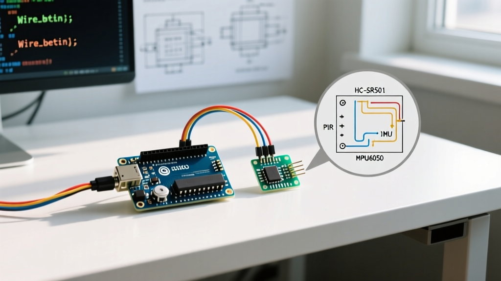
When makers and engineers search for an Arduino move sensor, they are typically referring to one of two fundamentally different components: a Passive Infrared (PIR) sensor like the HC-SR501 for detecting human motion, or an Inertial Measurement Unit (IMU) like the MPU6050 for tracking the physical movement, tilt, and acceleration of an object. While both are staples in the prototyping world, they suffer from entirely different failure modes.
As of 2026, the maker ecosystem has heavily shifted toward 3.3V logic architectures (such as the Arduino Nano 33 IoT, ESP32-S3, and Raspberry Pi Pico). This transition has introduced a new wave of compatibility issues with legacy 5V sensors, leading to widespread confusion when a movement sensor seemingly 'stops working.' In this comprehensive troubleshooting guide, we will dissect the exact hardware and software edge cases that cause PIR and IMU sensors to fail, providing actionable, component-level solutions.
⚠️ The Golden Rule of PIR Sensors: Never test an HC-SR501 immediately after applying power. The BISS0001 timing chip requires a 30-to-60-second initialization window to calibrate its internal baseline infrared noise floor. Testing it at second 5 will result in erratic, continuous HIGH outputs that mimic a broken sensor.
Part 1: Troubleshooting PIR Motion Sensors (HC-SR501 & AM312)
The HC-SR501 relies on a Fresnel lens to focus infrared radiation onto a pyroelectric sensor, which is then processed by a BISS0001 control IC. When your Arduino move sensor setup fails to detect human presence, the root cause is almost always analog noise or logic-level mismatching.
Symptom 1: Continuous False Triggers (Output Stuck HIGH)
If your serial monitor shows a relentless stream of 'Motion Detected' messages even in an empty room, you are likely dealing with power supply noise or environmental interference.
- The LDO Noise Issue: Cheap HC-SR501 modules use low-quality linear voltage regulators (LDOs) to step down 5V to 3.3V for the BISS0001 chip. Switching noise from your Arduino's USB power can couple into this line. Fix: Solder a 100µF electrolytic capacitor and a 0.1µF ceramic decoupling capacitor directly across the VCC and GND pins on the sensor PCB.
- Thermal & RF Interference: PIR sensors detect changes in IR signatures. Placing the sensor near a Wi-Fi router, a fluorescent ballast, or an HVAC vent will cause false triggers. Fix: Relocate the sensor at least 1.5 meters away from RF emitters and heat sources.
- Missing Ground Reference: If you are powering the PIR from a separate battery pack but forgot to tie the battery GND to the Arduino GND, the OUT pin will float, causing the Arduino's internal pull-up/pull-down resistors to read phantom voltage spikes.
Symptom 2: Sensor Never Triggers (Stuck LOW)
When the sensor is completely blind to movement, check the physical hardware configuration before blaming your code.
- Mode Jumper Setting: Underneath the HC-SR501 dome, there is a 3-pin header with a jumper cap. If set to 'L' (Single Trigger / Non-repeatable), the sensor will output HIGH for the duration set by the delay potentiometer, then go LOW for a 2.5-second lockout period, ignoring all motion. Move the jumper to 'H' (Repeatable Trigger) for standard Arduino polling.
- Potentiometer Tuning: The two onboard potentiometers control Sensitivity (Sx) and Time Delay (Tx). If the Sensitivity pot is turned fully counter-clockwise, the detection range drops to nearly zero. Turn it clockwise to increase the range up to 7 meters.
- Fresnel Lens Removal: The white plastic dome is not just a protective cover; it is a multi-faceted lens that creates distinct 'detection zones.' Movement is only registered when a heat source crosses between these zones. Operating the sensor without the lens will render it practically blind.
Symptom 3: The 3.3V Logic Mismatch (ESP32 / Nano 33 IoT)
If you are using a 3.3V Arduino board in 2026, feeding a 5V HC-SR501 output directly into your GPIO pin can cause silent failures or, worse, fry your microcontroller's input protection diodes. The HC-SR501 outputs roughly 3.5V to 4V when HIGH. While some ESP32 pins are 5V tolerant, many are not. Use a simple voltage divider (a 2.2kΩ resistor in series with the signal, and a 3.3kΩ resistor to ground) to safely step the logic level down to 3.3V.
Part 2: Troubleshooting IMU Movement Sensors (MPU6050 / ADXL345)
When tracking the physical movement of a robot arm, a drone, or a vehicle, makers rely on the MPU6050 (a 6-axis accelerometer and gyroscope). Unlike PIR sensors, IMUs communicate via the I2C bus, introducing a completely different set of digital communication hurdles.
Symptom 1: I2C Scanner Finds Nothing (0x68 / 0x69 Missing)
If your Arduino I2C scanner sketch returns 'No I2C devices found,' your move sensor is effectively disconnected at the protocol level.
- Missing Pull-Up Resistors: The I2C protocol requires pull-up resistors on both SDA and SCL lines. While some premium breakout boards include onboard 4.7kΩ pull-ups, bare-bones GY-521 modules often omit them to save costs. Fix: Install 4.7kΩ resistors between the SDA/SCL lines and your Arduino's VCC (3.3V or 5V, matching your logic level). For deeper technical context on I2C bus requirements, refer to the official Arduino Wire Library documentation.
- The AD0 Pin Float: The MPU6050's I2C address is determined by the AD0 pin. If AD0 is LOW (connected to GND), the address is 0x68. If HIGH, it is 0x69. If left floating, electromagnetic interference can cause the chip to randomly switch addresses mid-operation. Always tie AD0 explicitly to GND.
- Counterfeit Silicon: The market is flooded with cloned MPU6050 chips that fail to acknowledge their own I2C addresses. If wiring is verified, swap the module.
Symptom 2: Noisy, Drifting, or 'Jittery' Movement Data
If your serial plotter shows erratic spikes when the sensor is sitting perfectly still on a desk, you are experiencing high-frequency vibration coupling or improper internal filtering.
The MPU6050 features an internal Digital Low Pass Filter (DLPF). By default, register 0x1A is set to 0x00, which configures the accelerometer bandwidth to 260Hz. This is far too sensitive for most robotics applications, picking up the microscopic vibrations of a desk or the PWM whine of nearby motors.
The Fix: Write to the DLPF register during your setup routine. According to the TDK InvenSense MPU-6050 Product Specification, setting register 0x1A to 0x03 limits the bandwidth to 42Hz with a 4.9ms delay. This effectively smooths out mechanical noise while preserving the ability to track human-scale movement.
// Arduino C++ Snippet for DLPF Configuration
Wire.beginTransmission(0x68);
Wire.write(0x1A); // DLPF_CFG Register
Wire.write(0x03); // 42Hz Bandwidth
Wire.endTransmission(true);
Sensor Comparison Matrix: Choosing the Right 'Move' Sensor
Not all movement is created equal. Selecting the wrong sensor for your environment will lead to endless troubleshooting. Use this matrix to verify you have the correct hardware for your 2026 project requirements.
| Sensor Model | Detection Type | Best Use Case | Blind Spots & Limitations | Approx. Cost (2026) |
|---|---|---|---|---|
| HC-SR501 | Passive Infrared (PIR) | Security alarms, room occupancy, automated lighting. | Cannot detect stationary humans; triggered by heat sources. | $1.50 - $2.50 |
| RCWL-0516 | Microwave Doppler Radar | Through-wall motion detection, harsh/dusty environments. | Extremely sensitive; detects movement through drywall and wood. | $2.00 - $3.50 |
| MPU6050 | 6-Axis IMU (Accel/Gyro) | Robot balancing, drone stabilization, gesture tracking. | Suffers from gyroscope drift over time; requires sensor fusion (Kalman filter). | $3.00 - $5.00 |
| ADXL345 | 3-Axis Accelerometer | Tap detection, tilt sensing, drop-freefall logging. | No rotational tracking (gyroscope); lower resolution for micro-movements. | $4.50 - $7.00 |
Advanced Edge Case: The BISS0001 Timing Capacitor Hack
For advanced makers building custom PCBs or modifying the HC-SR501 for ultra-low-power battery applications, the standard timing components are a hindrance. The delay time (Tx) is governed by a resistor and capacitor connected to pins 15 and 16 of the BISS0001 timing IC. The stock potentiometer limits the maximum delay to roughly 200 seconds. By desoldering the stock timing capacitor and replacing it with a higher value (e.g., swapping the 10nF cap for a 47nF cap), you can extend the 'ON' time of the sensor to over 15 minutes per trigger, which is highly useful for off-grid solar lighting projects where frequent MCU wake-ups would drain the battery.
Summary Checklist for the Workbench
Before discarding a seemingly broken Arduino move sensor, run this 60-second diagnostic checklist:
- Power: Is the VCC stable? (Measure with a multimeter; USB droop below 4.5V kills PIR reliability).
- Ground: Do the sensor and the Arduino share a common ground?
- Logic: Are you feeding a 5V signal into a 3.3V pin without a level shifter or voltage divider?
- I2C: Are 4.7kΩ pull-up resistors present on SDA/SCL? Is the AD0 pin tied to GND?
- Environment: Is the PIR facing an HVAC vent? Is the IMU mounted on a dampening pad to prevent high-frequency vibration coupling?
By understanding the underlying physics of infrared zoning and the digital requirements of the I2C bus, you can transform erratic, unreliable sensor data into robust, production-ready movement tracking.