
Why Choose an I2C Display for Arduino?
If you are building your first microcontroller project, you have likely encountered the classic 16x2 character LCD. While the traditional parallel version of this screen works well, it requires at least six digital I/O pins just to display text. When you are working with a pin-constrained board or need those GPIOs for sensors and motors, this is a massive bottleneck. This is exactly why finding a reliable i2c display for arduino is a rite of passage for every maker.
By using an I2C (Inter-Integrated Circuit) backpack attached to the back of the LCD, the communication protocol is reduced to just two data lines: SDA (Serial Data) and SCL (Serial Clock), plus power and ground. This frees up your microcontroller's pins while maintaining full control over the screen's text, custom characters, and backlight.
| Feature | Standard Parallel LCD (HD44780) | I2C LCD (with PCF8574 Backpack) |
|---|---|---|
| GPIO Pins Required | 6 (RS, EN, D4, D5, D6, D7) | 2 (SDA, SCL) |
| Wiring Complexity | High (prone to loose breadboard connections) | Low (simple 4-pin JST or Dupont cable) |
| Code Complexity | Moderate (requires manual pin mapping) | Low (auto-detection libraries available) |
| Typical 2026 Cost | $4.50 - $6.00 | $3.00 - $5.00 (Clone), $14.95 (Adafruit) |
Required Hardware and 2026 Pricing
To follow this tutorial, you will need a standard HD44780-compatible LCD equipped with an I2C expander backpack. The vast majority of budget displays on Amazon or AliExpress use the PCF8574 or PCF8574A I/O expander chip manufactured by NXP or Texas Instruments.
- 16x2 or 20x4 LCD with I2C Backpack: $3.50 to $5.00 for generic clones. Ensure the backpack is pre-soldered to save time.
- Microcontroller: Arduino Uno R3, Nano, or ESP32.
- Jumper Wires: 4x Female-to-Male Dupont wires.
- Logic Level Converter (Optional): Required if you are using a 3.3V board like the ESP32 or Raspberry Pi Pico ($1.50).
Step 1: The I2C Address Trap (And How to Avoid It)
The number one reason beginners fail to get their I2C display working is an incorrect I2C address. Unlike SPI devices that use Chip Select pins, I2C relies on a hardcoded hexadecimal address.
Backpacks using the PCF8574 chip typically default to 0x27. However, backpacks using the PCF8574A chip default to 0x3F. If you hardcode the wrong address into your sketch, the screen will simply remain blank or show solid white blocks. To solve this, we use an I2C Scanner sketch before writing our main code.
Running the I2C Scanner
Upload the following minimal sketch to your Arduino to scan the I2C bus. This leverages the built-in Arduino Wire Library Reference to probe all 127 possible addresses.
#include <Wire.h>

void setup() {
  Wire.begin();
  Serial.begin(9600);
  while (!Serial); // Wait for serial monitor
  Serial.println("\nI2C Scanner");
}

void loop() {
  byte error, address;
  int nDevices = 0;
  Serial.println("Scanning...");
  for(address = 1; address < 127; address++ ) {
    Wire.beginTransmission(address);
    error = Wire.endTransmission();
    if (error == 0) {
      Serial.print("I2C device found at address 0x");
      if (address < 16) Serial.print("0");
      Serial.print(address, HEX);
      Serial.println("  !");
      nDevices++;
    }
  }
  if (nDevices == 0) Serial.println("No I2C devices found\n");
  delay(5000); // Wait 5 seconds before next scan
}
Open your Serial Monitor at 9600 baud. Note the address printed (e.g., 0x27 or 0x3F). You will need this for the next steps.
Step 2: Wiring the I2C Backpack
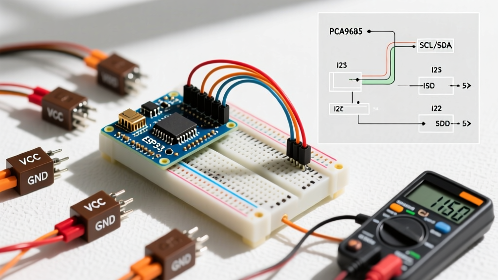
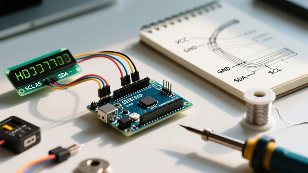
Wiring an I2C display for Arduino is remarkably straightforward. The backpack exposes four pins: GND, VCC, SDA, and SCL.
| I2C Backpack Pin | Arduino Uno / Nano (5V) | ESP32 / RP2040 (3.3V) | Function |
|---|---|---|---|
| GND | GND | GND | Common Ground Reference |
| VCC | 5V | 5V (VIN) | Power for LCD & Backlight |
| SDA | A4 (or dedicated SDA) | GPIO 21 | Serial Data Line |
| SCL | A5 (or dedicated SCL) | GPIO 22 | Serial Clock Line |
Expert Warning on 3.3V Logic: The HD44780 LCD and the PCF8574 backpack require 5V to operate correctly. If you power the VCC pin with 3.3V, the screen will likely remain blank due to insufficient voltage for the liquid crystals. Furthermore, pulling the SDA/SCL lines up to 5V on a 3.3V microcontroller like the ESP32 can permanently damage the GPIO pins over time. For 3.3V boards, use a bi-directional logic level converter on the SDA/SCL lines, or purchase a specialized 3.3V I2C LCD module.
Step 3: The Modern Library Approach
For years, the community relied on the LiquidCrystal_I2C library by Frank de Brabander. However, as of 2026, this library is largely considered legacy. It requires manual hex-mapping of the backpack's internal pins to the LCD pins, which varies wildly between cheap clone manufacturers.
Instead, the industry standard is now the hd44780 library maintained by Bill Perry. It is vastly superior because it features auto-detection for both the I2C address and the internal pin mapping, completely eliminating the blank screen issue caused by mismatched backpacks.
Installation and Code
- Open the Arduino IDE and navigate to Sketch > Include Library > Manage Libraries.
- Search for
hd44780by Bill Perry and install it. - Navigate to File > Examples > hd44780 > ioClass > hd44780_I2Cexp > HelloWorld.
Here is a streamlined version of the code utilizing the modern auto-config class:
#include <Wire.h>
#include <hd44780.h>
#include <hd44780ioClass/hd44780_I2Cexp.h>

// Auto-detect address and pin mapping
hd44780_I2Cexp lcd;

const int LCD_COLS = 16;
const int LCD_ROWS = 2;

void setup() {
  lcd.begin(LCD_COLS, LCD_ROWS);
  lcd.print("Electrical Flux");
  lcd.setCursor(0, 1);
  lcd.print("I2C Tutorial");
}

void loop() {
  // Blinking cursor example
  lcd.setCursor(14, 1);
  lcd.cursor();
  delay(500);
  lcd.noCursor();
  delay(500);
}
Real-World Troubleshooting & Edge Cases
Even with auto-detecting libraries, hardware quirks can cause issues. Here is how to diagnose the most common edge cases encountered in the field.
1. The Screen is Lit, But Shows Solid White Blocks
This is almost never a code issue. On the back of the I2C backpack, there is a small blue potentiometer (trimpot). This controls the V0 (Contrast) voltage. Take a small Phillips or flathead screwdriver and turn this pot slowly while the Arduino is powered. You will see the text appear as the voltage threshold aligns with the liquid crystal polarization.
2. The Backlight is Off
Inspect the top-left corner of the I2C backpack. Many manufacturers include a jumper cap bridging two pins labeled LED or Backlight. If this jumper is removed, the backlight circuit is broken. Simply bridge the two pins with a jumper cap or a drop of solder to enable the backlight permanently.
3. Display Freezes or Shows Garbage Characters
I2C is highly susceptible to electromagnetic interference (EMI) and capacitance over long wire runs. If your LCD is connected via wires longer than 30cm, the signal edges degrade, causing the PCF8574 chip to lock up. According to the Texas Instruments I2C Pull-Up Resistor Application Note, longer traces increase bus capacitance. To fix this, solder 4.7kΩ pull-up resistors between the SDA/SCL lines and the 5V VCC line directly at the I2C backpack to sharpen the signal rise times.
4. Multiple Devices on the Same Bus
If you are connecting your I2C display alongside an OLED screen, an MPU6050 accelerometer, and an RTC module, you might encounter address collisions. You can reference Adafruit's Comprehensive I2C Address List to map out your bus. If your LCD's address conflicts with another sensor, you can bridge the A0, A1, or A2 solder pads on the PCF8574 backpack to shift its address to one of 8 available slots.
Summary
Integrating an i2c display for arduino projects is one of the most rewarding upgrades a beginner can make. By moving away from legacy libraries and embracing modern auto-configuring tools like hd44780, you eliminate hours of frustrating hex-mapping. Pay close attention to your power delivery, respect 3.3V logic limits, and always keep a small screwdriver handy for the contrast pot. With these fundamentals mastered, your microcontroller projects will have a clean, professional interface ready for any sensor data you throw at it.