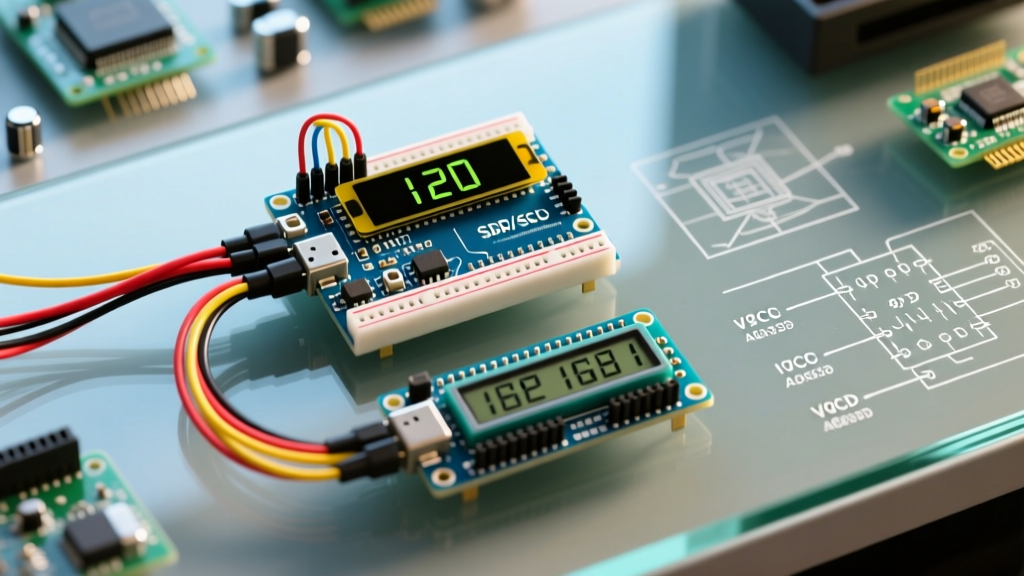

The Multi-Peripheral Display Bottleneck
Integrating multiple screens into a single microcontroller project is a rite of passage for advanced DIY electronics enthusiasts. However, executing a reliable dual display Arduino setup—such as pairing a graphical OLED for telemetry charts with a character LCD for system logs—exposes the hidden limitations of the I2C bus. When you daisy-chain displays, you are no longer just writing code; you are managing bus capacitance, pull-up resistor networks, and strict SRAM framebuffer limits.
In this guide, we will bypass the generic tutorials that assume perfect conditions. Instead, we will engineer a robust multi-peripheral display architecture using modern 2026 hardware, addressing the exact failure modes that cause screen flickering, I2C lockups, and memory crashes.
2026 Hardware BOM & Pricing
For this build, we are moving away from the legacy ATmega328P (Arduino Uno R3) due to its crippling 2KB SRAM limitation. The modern baseline for multi-display setups is the Arduino Nano ESP32, offering 320KB of SRAM and dual-core processing for under $20.
| Component | Specific Model / IC | Default I2C Address | Est. Price (2026) |
|---|---|---|---|
| Microcontroller | Arduino Nano ESP32 | N/A (Master) | $18.00 |
| Graphical Display | 1.3" SH1106 I2C OLED (128x64) | 0x3C | $5.50 |
| Character Display | 20x4 I2C LCD w/ PCF8574T Backpack | 0x27 | $6.00 |
| Bus Multiplexer | TCA9548A I2C Mux Module | 0x70 | $3.50 |
I2C Bus Architecture & Address Collisions
The most common point of failure in a multi-screen Arduino project is an I2C address collision. While the SH1106 OLED defaults to 0x3C, the 20x4 LCD backpacks are notoriously inconsistent. According to Adafruit's Master I2C Address List, PCF8574T backpacks use 0x27, but PCF8574AT variants use 0x3F. Worse, some cheap OLEDs and LCDs share the exact same hardcoded address with no jumper pads to change it.
The TCA9548A Multiplexer Solution
Rather than risking bus collisions or attempting to desolder and rewire address pads, professional multi-peripheral setups utilize the TCA9548A I2C Multiplexer. This $3.50 module acts as a traffic cop, creating up to 8 virtual I2C buses. You connect both displays to separate channels on the mux, allowing you to use identical displays (even with identical addresses) on the same Arduino without conflict.
Step-by-Step Wiring Matrix
When wiring multiple displays, power distribution is just as critical as data lines. A 20x4 LCD with an LED backlight can draw up to 120mA, while a 1.3" OLED draws roughly 20mA. Combined, they pull 140mA. If you are powering your Nano ESP32 via the VIN pin with a 9V battery, the onboard linear regulator will overheat and trigger thermal shutdown at around 150mA. Always power high-draw backlights directly from the 5V USB line or an external buck converter.
- VCC (OLED & Mux): Connect to Nano ESP32 3.3V pin (The ESP32 is natively 3.3V logic; feeding 5V to the SDA/SCL pins without level shifting will degrade the SoC over time).
- VCC (LCD Backpack): Connect to 5V source (Required for the LCD contrast and backlight).
- GND: Common ground across all modules and the Arduino.
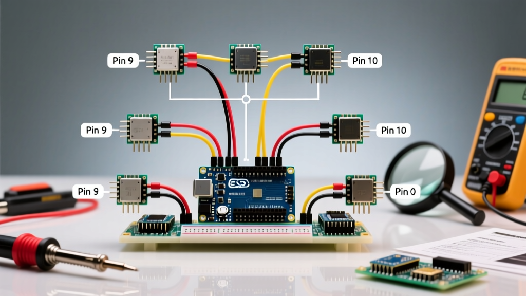
- SDA / SCL (Displays): Wire to the SDA0/SCL0 and SDA1/SCL1 channels on the TCA9548A Mux.
- SDA / SCL (Mux to Arduino): Wire Mux SDA to Nano ESP32 A4, and Mux SCL to A5.
The 400pF Capacitance Trap (Expert Insight)
The I2C specification strictly limits total bus capacitance to 400pF. Every jumper wire, breadboard row, and display module adds parasitic capacitance. A standard 20x4 LCD module adds roughly 15pF, and long ribbon cables can add 10pF per foot. If your wiring exceeds 400pF, the square waves on the SDA/SCL lines degrade into rounded slopes, causing the Arduino to misread bits and throw NACK errors.
Pro-Tip: If your dual display setup experiences random lockups or missing characters, do not immediately blame the code. Lower the I2C clock speed from Fast Mode (400kHz) to Standard Mode (100kHz) by adding Wire.setClock(100000); in your setup loop. This gives the voltage more time to rise against the parasitic capacitance, stabilizing the bus.
SRAM Management: Framebuffers vs. Page Buffers
Driving a 128x64 OLED requires a 1024-byte framebuffer (128 * 64 / 8 bits). If you use the standard Adafruit GFX Graphics Library, it allocates this 1KB block in SRAM immediately upon initialization. On a legacy Arduino Uno (2KB total SRAM), adding a second display or a few sensor libraries will instantly cause a stack collision and reset the MCU.
While the Arduino Nano ESP32 has 320KB of SRAM (making the 1KB buffer trivial), writing optimized code ensures your project remains portable and stable. For multi-display setups, we recommend the U8g2 Library.
Why U8g2 Wins for Multi-Peripheral Builds
- Page Buffer Mode: Instead of holding the entire 1024-byte screen in memory, U8g2 renders the display in 8-row 'pages', requiring only 128 bytes of SRAM.
- U8x8 Sub-library: For the 20x4 character LCD, U8g2 includes the U8x8 class, which bypasses graphics entirely and sends raw ASCII bytes directly to the HD44780 controller, using practically zero SRAM.
- Native Mux Support: U8g2 includes built-in functions to toggle TCA9548A channels without requiring manual Wire.h bitwise operations.
Troubleshooting Common Multi-Display Failures
Even with perfect wiring, multi-peripheral I2C setups present unique edge cases. Use this diagnostic matrix to resolve anomalies:
- Symptom: OLED works, but LCD shows solid white boxes on the top row.
Root Cause: The LCD backlight is drawing too much current, causing a voltage drop on the 5V rail, which resets the HD44780 controller logic while the backlight stays on.
Fix: Add a 100µF electrolytic capacitor across the LCD's VCC and GND pins to stabilize local voltage. - Symptom: Both displays work individually, but freeze when initialized together.
Root Cause: Pull-up resistor collision. Most breakout boards include 10kΩ or 4.7kΩ pull-up resistors on the SDA/SCL lines. Wiring them in parallel on the same I2C bus drops the total resistance (e.g., two 4.7kΩ resistors in parallel = 2.35kΩ). This exceeds the 3mA sink current limit of the ESP32's I2C pins.
Fix: Use the TCA9548A multiplexer to isolate the buses, or physically desolder the SMD pull-up resistors from one of the display modules. - Symptom: Wire.h hangs indefinitely on
Wire.endTransmission().
Root Cause: A slave device crashed and is holding the SDA line LOW, locking the I2C bus.
Fix: Implement a hardware watchdog timer (WDT) or send 9 clock pulses on the SCL line via GPIO toggling during setup to force the stuck slave to release the SDA line.
Final Thoughts on Peripheral Scaling
Running a dual display Arduino setup is less about writing complex graphics code and more about respecting the electrical realities of the I2C bus. By leveraging an ESP32-based microcontroller, isolating bus capacitance with a TCA9548A multiplexer, and utilizing page-buffered libraries like U8g2, you can scale your sensor and peripheral integrations reliably. Always measure your current draw and verify your pull-up resistor networks before finalizing your enclosure, and your multi-screen dashboard will operate flawlessly in the field.