
The Hidden Physics of Stepper Control
Most beginner tutorials on controlling stepper motors with Arduino treat the motor and driver as a black box. They instruct you to wire a NEMA 17 to an A4988 driver, turn a potentiometer blindly, and call a step() function. This approach inevitably leads to missed steps, overheated driver ICs, and stalled carriages. As of 2026, while newer silent drivers like the TMC2209 are popular, the Allegro A4988 remains the most widely deployed, cost-effective ($2 to $4 per module) stepper driver in DIY CNC and 3D printing. To achieve reliable motion, you must stop guessing and start reading the datasheets.
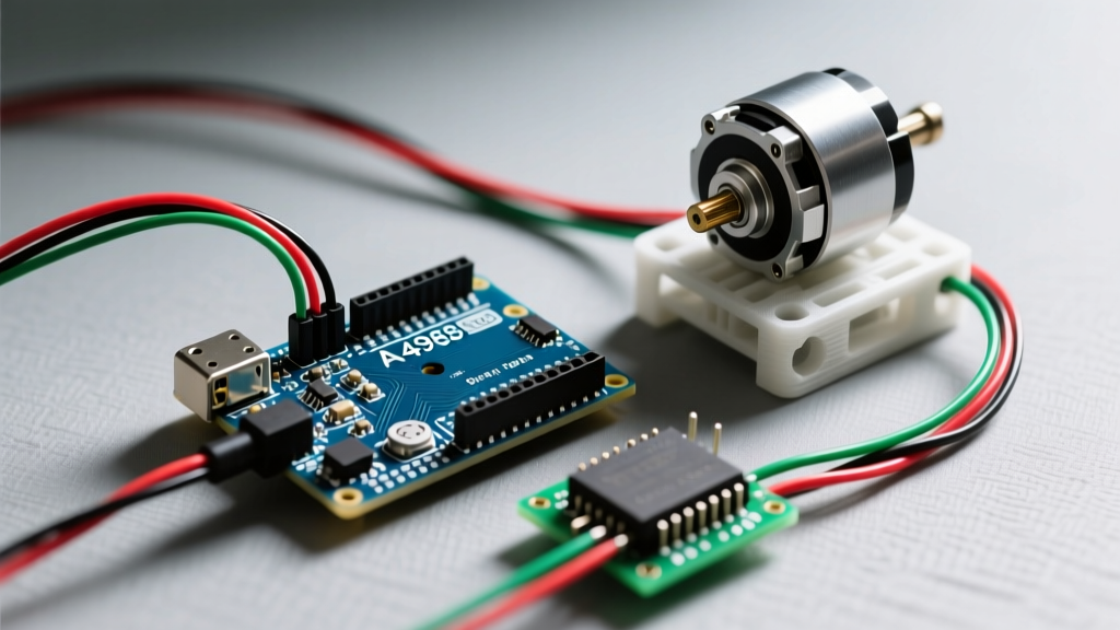
This guide decodes the critical specifications from the StepperOnline 17HS4401 (NEMA 17) motor datasheet and the Allegro A4988 driver datasheet, translating raw electrical limits into actionable Arduino code and hardware configurations.
Decoding the NEMA 17 (17HS4401) Datasheet
The 17HS4401 is a standard bipolar stepper motor costing around $14 to $18. Its datasheet provides the electrical boundaries that dictate how fast and how hard the Arduino can push it.
Holding Torque vs. Dynamic Torque
The datasheet highlights a holding torque of 40 N·cm (56.7 oz-in). This is the maximum torque the motor can exert to hold a position when energized at its rated current. However, dynamic torque (the torque available while moving) drops significantly as speed increases. If your Arduino code demands rapid acceleration, the available dynamic torque will fall below the inertia of your load, resulting in skipped steps.
The Inductance Bottleneck
The most misunderstood spec in the motor datasheet is phase inductance (3.8 mH) and phase resistance (1.8 Ω). Together, they create an L/R time constant ($\tau = L/R$), which is roughly 2.11 milliseconds. This means it takes over 2ms for the current in the coil to reach its target level when voltage is applied. If your Arduino sends step pulses faster than the coil can energize, torque collapses. This is why we drive steppers with higher voltages (12V or 24V) rather than the motor's rated 2.7V—the higher voltage forces current through the inductive coil faster, bypassing the L/R time constant limit.
Translating Specs to the A4988 Driver Datasheet
The A4988 is a constant-current chopper driver. It uses a sense resistor to monitor current and rapidly switches the voltage on and off (chopping) to maintain a steady current limit, protecting the motor from the 12V or 24V supply.
Calculating Vref (The Current Limit)
According to the Allegro A4988 datasheet, the trip current ($I_{TripMAX}$) is determined by the reference voltage ($V_{REF}$) and the sense resistor ($R_S$). The formula is:
$I_{TripMAX} = V_{REF} / (8 \times R_S)$
Most standard A4988 carrier boards use a 0.1 Ω sense resistor. The 17HS4401 motor is rated for 1.5A per phase. However, running an A4988 at 1.5A continuously without active cooling will trigger its internal thermal shutdown. We must derate the current by 30% for continuous operation, targeting 1.05A.
- Target Current: 1.05A
- Sense Resistor: 0.1 Ω
- Calculation: $V_{REF} = 1.05 \times 8 \times 0.1 = 0.84V$
Action Step: Use a multimeter to measure the voltage between the A4988 GND pin and the Vref potentiometer. Adjust the pot until you read exactly 0.84V before ever connecting the motor coils.
Microstepping and Timing Matrix
The A4988 supports up to 1/16th microstepping, which divides the standard 1.8° step (200 steps/rev) into 3200 steps per revolution. This smooths out low-speed resonance but requires faster pulse generation from the Arduino. Furthermore, the datasheet specifies strict timing constraints for the STEP pin.
| Microstep Resolution | MS1 | MS2 | MS3 | Steps per Rev | Min STEP Pulse Width ($t_{W(STEP)}$) |
|---|---|---|---|---|---|
| Full Step | Low | Low | Low | 200 | 1 µs |
| 1/2 Step | High | Low | Low | 400 | 1 µs |
| 1/8 Step | High | High | Low | 1600 | 1 µs |
| 1/16 Step | High | High | High | 3200 | 1 µs |
While the A4988 requires a minimum step pulse width of just 1 µs, an Arduino Uno running at 16MHz takes approximately 3.5 µs to execute a standard digitalWrite() command. Therefore, using standard Arduino functions is inherently safe for the A4988's timing requirements, though direct port manipulation is preferred for high-speed CNC applications to reduce jitter.
Arduino Implementation: Bridging Datasheet to Code
When controlling stepper motors with Arduino, raw digitalWrite loops fail to account for rotor inertia. If you command the motor to instantly jump to 1000 RPM, the magnetic field will rotate, but the physical rotor will lag behind and stall. You must use an acceleration profile.
The industry-standard AccelStepper library calculates trapezoidal speed profiles based on the physics of your specific setup. Here is how you configure it based on our datasheet findings:
#include <AccelStepper.h>

// Define pins (Step = 2, Dir = 3)
AccelStepper stepper(AccelStepper::DRIVER, 2, 3);

void setup() {
  // 1/8 microstepping = 1600 steps/rev
  stepper.setMaxSpeed(1600);

  // Acceleration must respect the 40 N·cm holding torque
  // and the mass of your specific carriage.
  // Start conservative at 800 steps/s^2 and tune upward.
  stepper.setAcceleration(800);

  stepper.setCurrentPosition(0);
  stepper.moveTo(3200); // Move exactly 2 revolutions
}

void loop() {
  stepper.run();
}
Edge Case: Mid-Band Resonance
Stepper motors suffer from a phenomenon called mid-band resonance, typically occurring between 150 and 300 RPM (roughly 500 to 1000 full steps per second). At this frequency, the rotor overshoots its target position and oscillates, potentially losing synchronization entirely. The motor datasheet won't explicitly give you a software fix for this, but the A4988 datasheet provides the hardware solution: Microstepping. By setting the driver to 1/8 or 1/16 microstepping, you dampen the magnetic field transitions, effectively eliminating the resonance stall zone.
Hardware Wiring and Failure Modes
Even with perfect code, improper wiring will destroy your setup. The most common catastrophic failure mode when controlling stepper motors with Arduino is disconnecting the motor coils while the driver is powered. The A4988 regulates current by switching the high-voltage supply. If the coil path is broken, the inductive kickback has nowhere to go, instantly overvolting and frying the driver's internal MOSFETs. Always power down the 12V/24V supply before touching the motor wiring.
Thermal Management Checklist
- Heatsink Application: The A4988 package has a thermal pad on the bottom. If your continuous current exceeds 1.0A, a stick-on heatsink is mandatory to keep the IC below its 165°C thermal shutdown threshold.
- Power Supply Sizing: A single 17HS4401 motor drawing 1.05A across two phases at 12V requires roughly 25W of power. For a standard 3D printer setup using three NEMA 17 motors, a 12V 10A (120W) power supply is the minimum safe baseline.
- Decoupling Capacitors: Place a 100µF electrolytic capacitor across the VMOT and GND pins on the A4988 carrier board. This absorbs voltage spikes generated by the inductive motor coils, protecting the driver IC.
Summary
Successfully controlling stepper motors with Arduino is an exercise in applied physics. By respecting the 17HS4401's inductance limits, calculating the A4988's Vref to exactly 0.84V for thermal safety, and utilizing acceleration profiles to manage rotor inertia, you transition from simply spinning a motor to engineering a reliable, precision motion system.