
Mastering Actuator Control: The Complete Servo Interfacing Guide
When building robotic arms, pan-tilt camera mounts, or automated RC vehicles, mastering actuator control is essential. If you are researching how to connect servo motor to Arduino microcontrollers, you have likely encountered a maze of conflicting wiring diagrams and unexplained jitter issues. This guide strips away the fluff, providing exact wiring topologies, pulse-width modulation (PWM) timing specifications, and power delivery frameworks for both micro-servos and high-torque metal-gear models.
Unlike standard DC motors that spin continuously, RC (Radio Control) servos are closed-loop systems. They contain a DC motor, a gear train, and a potentiometer for positional feedback. By sending a precise PWM signal, you command the internal circuitry to move the output shaft to an exact angle and hold it there against physical resistance.
Bill of Materials (2026 Market Pricing)
Before wiring, you need to select the right actuator for your mechanical load. Here is a breakdown of the most common components used in beginner to intermediate projects.
| Component | Model / Specification | Avg Price (2026) | Best Use Case |
|---|---|---|---|
| Micro Servo | TowerPro SG90 (9g) | $2.50 - $3.50 | Lightweight linkages, sensor sweeping, RC plane flaps |
| Standard Servo | TowerPro MG996R (Metal Gear) | $9.00 - $12.00 | Robotic arms, steering mechanisms, heavy pan-tilt mounts |
| Microcontroller | Arduino Uno R4 Minima / R3 | $20.00 - $27.00 | Prototyping, PWM signal generation |
| Power Supply | 5V/6V 3A BEC or LM2596 Buck | $3.00 - $5.00 | Powering high-torque servos without browning out the MCU |
| Capacitor | 100µF - 470µF Electrolytic | $0.10 | Smoothing inductive voltage spikes |
The Physics of RC Servo PWM Timing
To understand how to connect servo motor to Arduino hardware successfully, you must understand the control signal. Standard hobby servos do not use analog voltage levels or I2C/SPI digital protocols. They rely on a 50 Hz Pulse Width Modulation (PWM) signal.
- Frequency: 50 Hz (One pulse every 20 milliseconds).
- Neutral (90°): 1.5 millisecond (1500 µs) HIGH pulse.
- Minimum (0°): 1.0 millisecond (1000 µs) HIGH pulse.
- Maximum (180°): 2.0 millisecond (2000 µs) HIGH pulse.
The Arduino Servo.h library handles this 50 Hz timing automatically in the background using hardware timers, freeing up your main loop to handle other logic.
Direct Wiring: The SG90 Micro Servo
The SG90 is the quintessential beginner servo. Its stall current is roughly 700mA, which allows it to be powered directly from the Arduino's 5V pin under very specific conditions.
Step-by-Step SG90 Pinout
- Signal Wire (Orange/Yellow): Connect to a PWM-capable digital pin on the Arduino (e.g., Pin 9). On the Uno R3 and R4, pins 3, 5, 6, 9, 10, and 11 support hardware PWM.
- VCC Wire (Red): Connect to the Arduino 5V pin.
- GND Wire (Brown/Black): Connect to the Arduino GND pin.
Critical Warning: If you are powering your Arduino Uno via a standard USB 2.0 port, the port is limited to 500mA. If the SG90 encounters mechanical resistance and approaches its 700mA stall current, it will exceed the USB limit, causing the Arduino's onboard polyfuse to trip or the microcontroller to brownout and reset. For reliable operation, power the Arduino via the DC barrel jack (7-12V) so the onboard NCP1117 voltage regulator can supply adequate current.
The High-Torque Trap: Powering the MG996R
A common and destructive beginner mistake is wiring a high-torque servo like the MG996R directly to the Arduino 5V pin. The MG996R can draw up to 2.5 Amps under stall conditions. The Arduino's onboard linear voltage regulator is typically rated for 800mA maximum (and much less without a heatsink). Connecting an MG996R directly will instantly overheat the regulator, potentially destroying the Arduino board and your computer's USB port.
The External Power Topology
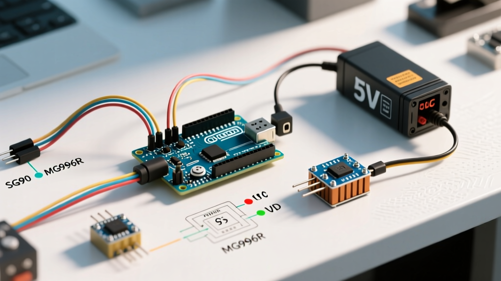
To safely interface high-torque servos, you must use an external power supply and establish a common ground.
- Connect the positive terminal of a 5V or 6V external power supply (like a 5V 3A BEC) directly to the servo's Red VCC wire.
- Connect the negative terminal of the external power supply to the servo's Brown GND wire.
- The Golden Rule: Run a jumper wire from the external power supply's negative terminal to one of the Arduino's GND pins. Without this common ground reference, the Arduino's PWM signal will float, resulting in erratic servo behavior or no movement at all.
- Connect the servo's Signal wire to Arduino Pin 9.
Pro-Tip: The Decoupling Capacitor Hack
Servos are inductive loads. When the internal DC motor starts and stops rapidly, it creates voltage spikes and sudden current draws that can introduce noise into your microcontroller's power rail, causing ADC (Analog-to-Digital Converter) inaccuracies or system resets. Soldering a 100µF to 470µF electrolytic capacitor directly across the VCC and GND wires at the servo connector acts as a local energy reservoir, absorbing spikes and smoothing out the current delivery.
Arduino C++ Implementation
The official Arduino Servo Library Documentation provides a robust API for generating the required PWM signals. Below is a production-ready implementation that includes a safe startup sequence.
#include <Servo.h>

Servo myServo;
const int servoPin = 9;

void setup() {
  myServo.attach(servoPin, 544, 2400);
  // The 544 and 2400 parameters calibrate the min/max pulse widths
  // to match the specific physical limits of your servo model.

  myServo.write(90); // Start at neutral position
  delay(1000);       // Allow time for the servo to reach neutral
}

void loop() {
  // Sweep from 0 to 180 degrees
  for (int pos = 0; pos <= 180; pos += 1) {
    myServo.write(pos);
    delay(15); // 15ms delay controls the speed of the sweep
  }

  delay(1000); // Pause at 180 degrees

  // Return to 0 degrees
  for (int pos = 180; pos >= 0; pos -= 1) {
    myServo.write(pos);
    delay(15);
  }

  delay(2000); // Pause before repeating
}
Advanced Control: writeMicroseconds()
While write(degrees) is sufficient for basic projects, advanced robotics require higher precision. The writeMicroseconds() function allows you to bypass the library's internal degree-to-pulse mapping. For example, myServo.writeMicroseconds(1500); sends an exact 1.5ms pulse, commanding the exact mechanical center of the potentiometer, eliminating rounding errors inherent in the 0-180 degree mapping.
Troubleshooting Matrix: Solving Servo Jitter and Failures
Even with correct wiring, environmental and electrical factors can cause erratic behavior. Use this diagnostic matrix to resolve common issues.
| Symptom | Root Cause | Engineering Fix |
|---|---|---|
| Continuous low-frequency jittering | Insufficient current delivery causing micro-brownouts on the MCU. | Upgrade to a higher-amperage BEC; add a 470µF decoupling capacitor. |
| Servo moves to random angles on startup | Arduino PWM pins float during the bootloader sequence before attach() is called. | Use a 10kΩ pull-down resistor between the Signal pin and GND. |
| Stripped internal gears | Mechanical binding or exceeding the physical travel limits. | Use attach(pin, min, max) to software-limit the travel; upgrade to metal-gear (MG) variants. |
| Servo hums but does not move | Signal wire connected, but VCC/GND missing or common ground omitted. | Verify external power is active and GND is shared with the Arduino. |
Further Reading and Standards
Understanding the underlying standards of RC peripherals will make you a more effective embedded systems designer. For a deep dive into the history and electrical specifications of hobby servos, the Pololu RC Servo Introduction Guide provides excellent oscilloscope captures and teardown analyses of internal feedback loops.
By respecting the current limitations of your microcontroller, implementing proper common-ground topologies, and utilizing precise microsecond timing, you can reliably integrate any servo motor into your Arduino projects. Whether you are actuating a simple camera shutter or building a 6-DOF robotic arm, these foundational principles ensure smooth, jitter-free operation.