
The Quest for the Perfect Gyroscope Arduino Integration
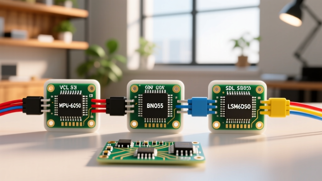
Integrating a gyroscope into an Arduino project is a rite of passage for robotics, drones, and motion-tracking enthusiasts. However, not all inertial measurement units (IMUs) are created equal. Selecting the right sensor dictates your processing overhead, power consumption, and ultimately, the stability of your closed-loop control systems. In this comprehensive component comparison, we evaluate the three most dominant sensors on the market for gyroscope Arduino applications: the legacy TDK InvenSense MPU-6050, the sensor-fusion powerhouse Bosch BNO055, and the modern, low-power STMicroelectronics LSM6DSO.
Whether you are building a self-balancing robot, a VR headset, or a low-power wearable, understanding the hardware quirks, I2C bus requirements, and onboard processing capabilities of these chips is critical. Let us dive into the silicon.
Head-to-Head Comparison Matrix
Before examining the architectural nuances, here is a high-level specification and pricing matrix based on current 2026 breakout board market averages.
| Feature | MPU-6050 (TDK) | BNO055 (Bosch) | LSM6DSO (ST) |
|---|---|---|---|
| Axis | 6-Axis (Gyro + Accel) | 9-Axis (Gyro + Accel + Mag) | 6-Axis (Gyro + Accel) |
| Onboard Fusion | DMP (Requires Firmware) | Hardware NDOF Fusion | Software/MLC Offload |
| Typical Breakout Price | $1.50 - $3.50 | $14.00 - $19.95 | $6.00 - $9.50 |
| I2C Addresses | 0x68 or 0x69 | 0x28 or 0x29 | 0x6A or 0x6B |
| Max I2C Speed | 400 kHz | 400 kHz | 1 MHz (I2C Fast+) |
| Active Current Draw | 3.9 mA | 13 mA (Fusion Active) | 0.55 mA (Normal Mode) |
The Budget Workhorse: TDK InvenSense MPU-6050
The MPU-6050 is arguably the most ubiquitous IMU in the Arduino ecosystem. Despite being an older design, its rock-bottom price and massive community support keep it relevant for hobbyist robotics and basic stabilization tasks.
Real-World Performance and Quirks
The MPU-6050 outputs raw angular velocity and acceleration data. To get usable orientation (pitch, roll, yaw), your Arduino must run a sensor fusion algorithm like Madgwick or Mahony. This consumes valuable CPU cycles on an ATmega328P (Arduino Uno), potentially interfering with high-frequency PID control loops.
Expert Insight: The MPU-6050 features a proprietary Digital Motion Processor (DMP). You can offload sensor fusion to the DMP by flashing a 3,060-byte firmware blob into its auxiliary memory at boot. However, this requires precise I2C timing. If your Arduino is interrupted during the 300ms DMP firmware upload sequence, the sensor will lock up and require a hard power cycle.
Failure Modes to Anticipate
- I2C Lockups: Cheap clone boards often omit the required 4.7kΩ pull-up resistors on the SDA and SCL lines. Without them, the I2C bus will float, causing the
Wire.hlibrary to hang indefinitely. - Yaw Drift: Because it lacks a magnetometer, the Z-axis (yaw) will drift at a rate of approximately 0.05° to 0.1° per second due to gyroscope integration bias. It is unsuitable for absolute heading navigation.
The Sensor Fusion King: Bosch BNO055
If your project requires absolute orientation without taxing your microcontroller, the Bosch BNO055 is the premium choice. It integrates a triaxial gyroscope, accelerometer, and magnetometer alongside an ARM Cortex-M0 core running Bosch's proprietary sensor fusion algorithms.
The NDOF Advantage
The BNO055's NDOF (Nine Degrees of Freedom) mode seamlessly merges magnetic north, gravity, and rotational velocity. You simply read the quaternion registers, and the chip hands you perfectly stabilized, drift-free orientation data. This makes it the undisputed champion for VR head tracking, autonomous rover navigation, and robotic arms requiring absolute spatial awareness.
Hardware Integration Warnings
Despite its brilliance, the BNO055 is notorious for a specific hardware quirk: I2C clock stretching. The internal MCU occasionally holds the SCL line low to buy time for calculations. Standard Arduino Wire.h implementations (and even some ESP32 I2C drivers) do not handle clock stretching gracefully, leading to timeout errors and corrupted data packets.
- Solution 1: Use the sensor in UART mode instead of I2C. The BNO055 supports standard serial communication, entirely bypassing clock stretching issues.
- Solution 2: If you must use I2C, implement a software reset routine that monitors for
Wire.endTransmission()timeouts and toggles the sensor's RST pin via a dedicated GPIO.
The Modern Contender: STMicroelectronics LSM6DSO
For wearable tech, battery-powered IoT nodes, and high-speed vibration analysis, the STMicroelectronics LSM6DSO represents the cutting edge of 6-axis IMU design. It offers a significantly lower noise floor and advanced power-saving features compared to the legacy MPU-6050.
Machine Learning Core (MLC) and FIFO
The LSM6DSO features a built-in Machine Learning Core (MLC) and a Finite State Machine (FSM). You can train a decision tree to recognize specific motion patterns (e.g., a specific gesture, a fall, or a motor vibration signature) and upload it to the sensor. The LSM6DSO will process the data internally and only wake your Arduino via an interrupt pin when the pattern is detected, allowing the main MCU to sleep for weeks on a coin cell battery.
Additionally, its 9KB FIFO buffer allows you to burst-read data at 6.66 kHz. This is invaluable for active noise cancellation or high-frequency PID tuning, as it prevents data loss if your Arduino is busy handling network requests or display rendering.
Mastering I2C Bus Design for IMUs
Regardless of which gyroscope Arduino setup you choose, I2C bus capacitance is the silent killer of motion projects. The I2C specification limits total bus capacitance to 400pF. Long wires, breadboard parasitic capacitance, and multiple sensors can easily exceed this, resulting in rounded square waves and corrupted bytes.
Calculating Pull-Up Resistors
Do not blindly rely on the 10kΩ pull-up resistors included on some breakout boards. For reliable 400kHz I2C communication with an Arduino, calculate your pull-ups based on bus capacitance:
- Short runs (< 10cm, single sensor): 4.7kΩ resistors are generally sufficient.
- Medium runs (10-30cm, or 2-3 sensors): Step down to 3.3kΩ or 2.2kΩ to provide more current and faster rise times.
- Long runs or high capacitance: Use an active I2C bus extender (like the PCA9600) or switch to SPI mode if the sensor supports it (both the MPU-6050 and LSM6DSO support SPI, which is immune to these capacitance limits).
Calibration and Drift Mitigation Strategies
MEMS gyroscopes suffer from turn-on bias and temperature-dependent drift. To achieve professional-grade results, implement a stationary calibration routine in your Arduino setup function.
- Mount the sensor in its final enclosure (thermal mass affects drift).
- Power on the system and enforce a mandatory 5-second stationary delay.
- Sample the raw gyroscope Z-axis (and X/Y) at 100Hz during this delay.
- Calculate the mean bias offset and subtract this value from all subsequent readings in your main loop.
- Monitor the onboard temperature sensor (all three chips provide this) and apply a linear temperature compensation curve if operating in varying outdoor environments.
Final Verdict: Which Sensor Should You Choose?
Your choice of gyroscope Arduino sensor must align with your project's constraints. Choose the MPU-6050 if you are building a low-budget, indoor balancing robot and are comfortable writing your own Madgwick filter code. Upgrade to the BNO055 if your application demands absolute, drift-free 3D heading (yaw) and you have the budget to absorb the $15+ breakout cost—just be prepared to manage its I2C clock stretching. Finally, deploy the LSM6DSO for battery-operated wearables, high-speed vibration monitoring, or when you want to leverage edge-computing via its onboard Machine Learning Core.