
The Reality of Flex Sensor "Libraries"
When searching for a flex sensor Arduino library, many beginners hit a wall. Unlike digital peripherals such as the BME280 or MPU6050 that communicate over I2C or SPI, standard resistive flex sensors (like the industry-standard Spectra Symbol FLX-01 series) are purely analog components. They do not have a digital "library" in the traditional sense. Instead, a robust flex sensor implementation requires a hardware signal conditioning circuit paired with a custom software DSP (Digital Signal Processing) driver to handle ADC noise, hysteresis, and environmental drift.
In this comprehensive guide, we will build a complete hardware and software driver for integrating a flex sensor with Arduino, ESP32, and Teensy ecosystems, updated for the high-resolution ADCs common in 2026 microcontroller designs.
Hardware Driver: Signal Conditioning & The Voltage Divider
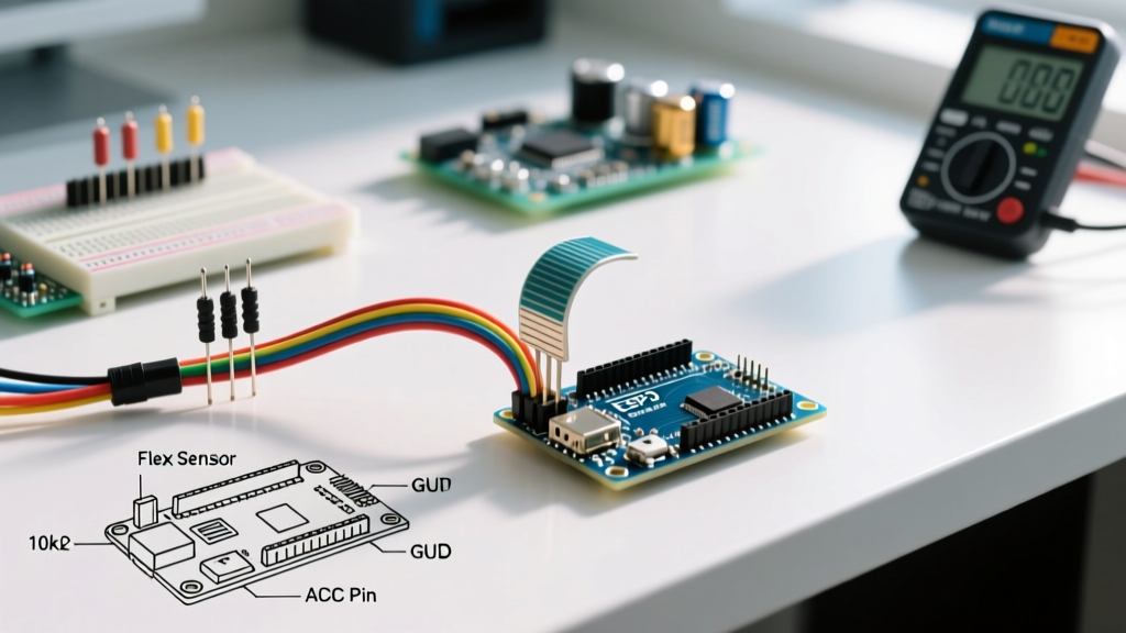
A flex sensor is essentially a variable resistor. The Spectra Symbol 2.2-inch model (FLX-01-2.2) typically measures around 10kΩ when flat, and increases to roughly 20kΩ–40kΩ when bent to 90 degrees. To read this with a microcontroller, we must convert the resistance change into a voltage change using a voltage divider network.
Component Selection & Tolerance
Do not use standard 5% carbon film resistors for your pull-down resistor. The inherent noise and thermal drift will compound the flex sensor's own hysteresis. Use a 1% tolerance metal film resistor. For a 2.2-inch sensor, a 10kΩ pull-down is standard. For the 4.5-inch sensor (which can reach 60kΩ+ when fully bent), a 22kΩ or 33kΩ pull-down provides a better voltage swing across the ADC range.
Expert Insight: ADC Impedance MismatchModern microcontrollers like the ESP32-S3 feature 12-bit ADCs, but their internal sampling capacitors require a low-impedance source. A flex sensor combined with a 10kΩ resistor creates a Thevenin equivalent resistance that can cause reading inaccuracies at high sampling rates. If you are sampling faster than 100Hz, buffer the voltage divider output with an op-amp (like the MCP6001) configured as a voltage follower before feeding it to the analog pin.
Software Driver: Building a Robust C++ Class
Raw analogRead() values from a flex sensor are notoriously noisy due to electromagnetic interference and the physical micro-vibrations of the sensor material. A proper software driver must implement an Exponential Moving Average (EMA) filter to smooth the data without introducing the severe latency associated with simple moving averages.
The C++ FlexSensor Driver Class
Below is a production-ready C++ class that acts as your software driver. It handles ADC resolution scaling (10-bit vs 12-bit) and applies an EMA filter.
class FlexSensor {
  private:
    uint8_t _pin;
    float _alpha;       // Smoothing factor (0.0 to 1.0)
    float _smoothedVal;
    int _adcMax;        // 1023 for Uno, 4095 for ESP32/Teensy
    bool _initialized;

  public:
    FlexSensor(uint8_t pin, int adcMax = 1023, float alpha = 0.15) {
      _pin = pin;
      _adcMax = adcMax;
      _alpha = alpha;
      _smoothedVal = 0;
      _initialized = false;
      pinMode(_pin, INPUT);
    }

    // Returns smoothed 0.0 to 1.0 ratio
    float readRatio() {
      int raw = analogRead(_pin);
      if (!_initialized) {
        _smoothedVal = raw;
        _initialized = true;
      } else {
        _smoothedVal = (_alpha * raw) + ((1.0 - _alpha) * _smoothedVal);
      }
      return _smoothedVal / _adcMax;
    }

    // Maps smoothed value to a specific degree range
    float readAngle(float flatVal, float bent90Val, float minAngle = 0, float maxAngle = 90) {
      float ratio = readRatio();
      // Constrain and map based on calibrated ADC boundaries
      float mapped = minAngle + (ratio - flatVal) * (maxAngle - minAngle) / (bent90Val - flatVal);
      return constrain(mapped, minAngle, maxAngle);
    }
};
Calibration Data Matrix
To use the readAngle() function, you must calibrate your specific sensor. Flex sensors have a manufacturing tolerance of up to ±30% in baseline resistance. Never rely on datasheet nominal values for precision robotics or animatronics. Run a calibration sketch to capture your specific flatVal and bent90Val ADC ratios.
| Bend Angle | Typical Resistance (2.2") | Voltage Out (5V, 10kΩ Pull-down) | Expected 10-bit ADC | Expected 12-bit ADC |
|---|---|---|---|---|
| 0° (Flat) | ~10,000 Ω | 2.50 V | ~512 | ~2048 |
| 45° | ~17,000 Ω | 1.85 V | ~379 | ~1517 |
| 90° | ~25,000 Ω | 1.43 V | ~292 | ~1170 |
Note: As the sensor bends, resistance increases, causing the voltage at the analog pin to drop. Your code must account for this inverse relationship.
Real-World Failure Modes & Edge Cases
Integrating a flex sensor into a commercial product or advanced DIY project introduces physical and electrical edge cases that standard tutorials ignore. Address these during your prototyping phase:
- The "Creep" Phenomenon: If you hold a flex sensor at a static 45-degree angle for 60+ seconds, the resistance will slowly drift upward by 5-10% due to the viscoelastic properties of the carbon-polymer ink. Solution: Do not use flex sensors for static, long-term positional holding. Use them for dynamic gesture recognition, or implement a software high-pass filter to ignore slow static drift.
- Solder Pad Delamination: The silver polymer traces on the sensor's tail are extremely heat-sensitive. Applying a standard 350°C soldering iron will instantly delaminate the pad, destroying the $15-$30 component. Solution: Use a specialized low-temperature soldering iron (under 180°C), conductive epoxy (like MG Chemicals 8331), or crimp the tail into a Molex ZIF (Zero Insertion Force) connector.
- Temperature Coefficient: Flex sensors exhibit a negative temperature coefficient (NTC). As ambient temperature rises, baseline resistance drops. If your project operates in uncontrolled environments (e.g., outdoor robotics in summer), you must pair the flex sensor with a thermistor and apply a temperature-compensation algorithm in your driver.
- Hysteresis: The sensor will output a slightly different resistance when returning to 0° from 90° compared to when it is moving from 0° to 90°. A mechanical return spring in your physical housing is highly recommended to force the sensor back to a hard mechanical stop, allowing your software to auto-zero the baseline on every release.
Authoritative References
- Arduino Official analogRead() Reference - Documentation on ADC sampling rates and pin impedance requirements.
- Spectra Symbol Flex Sensor Technical Data - Manufacturer specifications on bend radius limits, lifecycle testing, and resistance tolerances.
- SparkFun Voltage Divider Tutorial - Foundational mathematics for resistive signal conditioning networks.