
The Reality of Ultrasonic Sensor Integration
Learning how to wire ultrasonic sensor Arduino configurations is a rite of passage for embedded systems hobbyists and engineers alike. The ubiquitous HC-SR04 module, typically priced between $2.00 and $4.50 in 2026, offers an accessible entry point into time-of-flight (ToF) distance measurement. However, the transition from a theoretical breadboard schematic to a reliable, real-world deployment is rarely seamless. Engineers frequently encounter serial monitor outputs locked at '0 cm', erratic distance jumps, or complete microcontroller lockups.
This troubleshooting guide bypasses basic tutorials and dives deep into the electrical and acoustic failure modes of 40kHz ultrasonic transducers. Whether you are using a classic 5V Arduino Uno R3 or a modern 3.3V Arduino Nano ESP32, we will diagnose the exact hardware and timing bottlenecks causing your sensor to fail.
Baseline Wiring Topology: 5V vs. 3.3V Logic
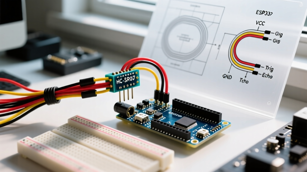
The most common point of failure when figuring out how to wire an ultrasonic sensor to an Arduino is logic level mismatch. The HC-SR04 requires a 5V power supply to drive its internal MAX232 equivalent chip and generate the 40kHz acoustic burst. However, modern microcontrollers often operate at 3.3V logic. Feeding a 5V Echo signal directly into a 3.3V GPIO pin will degrade the silicon over time or cause immediate latch-up.
| Microcontroller | Logic Level | Trigger Pin Wiring | Echo Pin Wiring | Power Supply |
|---|---|---|---|---|
| Arduino Uno R3 / R4 | 5V | Direct to GPIO | Direct to GPIO | 5V Pin |
| Arduino Nano ESP32 | 3.3V | Direct to GPIO | Voltage Divider Required | 5V Pin (or external) |
| Raspberry Pi Pico (RP2040) | 3.3V | Direct to GPIO | Voltage Divider Required | VBUS (5V) Pin |
Designing the Voltage Divider for 3.3V MCUs
To safely step down the 5V Echo pulse to a 3.3V-tolerant level, you must implement a resistor voltage divider. According to the Arduino Official Ultrasonic Sensor Guide, proper signal conditioning is critical for stable edge detection. Use a 2kΩ resistor (R1) in series with the Echo pin, and a 3.3kΩ resistor (R2) connecting the junction to GND. This yields an output voltage of approximately 3.11V (5V × [3.3 / (2 + 3.3)]), which registers as a clean HIGH on 3.3V logic without risking GPIO damage.
Symptom 1: Serial Monitor Reads '0' or Stalls Completely
If your serial output is stuck at '0 cm' or the Arduino appears to freeze entirely, the issue is almost always related to the pulseIn() function timing out. The HC-SR04 works by sending a 10µs HIGH pulse to the Trigger pin, then waiting for the Echo pin to go HIGH. If the sensor fails to detect a returning acoustic wave (due to a disconnected wire, a dead transducer, or an out-of-range target beyond 400cm), the Echo pin never goes HIGH.
The Timeout Trap
By default, the Arduino pulseIn() function waits for up to 1 second (1,000,000 microseconds) before giving up. If your sensor is miswired, this 1-second delay will severely bottleneck your main loop, making it appear as though the microcontroller has crashed.
- The Fix: Always implement a hardcoded timeout parameter. Use
pulseIn(echoPin, HIGH, 30000)to cap the wait time at 30 milliseconds (roughly equivalent to 5 meters). This ensures your loop continues to execute even if the acoustic echo is lost. - Hardware Check: Verify that the Trigger pin is not accidentally configured as
INPUT_PULLUP. It must be a standardOUTPUT. Furthermore, ensure your breadboard ground rails are continuous; a split ground rail is a notorious culprit for floating Echo signals.
Symptom 2: Erratic Distance Jumps (e.g., 15cm to 140cm)
When the sensor is pointed at a static wall but the serial monitor shows wild fluctuations, you are experiencing power rail sag and acoustic crosstalk. During the 40kHz transmission burst, the HC-SR04 can draw transient currents up to 15mA. If you are powering the sensor through long, thin 24AWG breadboard jumper wires, the parasitic resistance of the wires causes a momentary voltage drop at the sensor's VCC pin.
The Decoupling Capacitor Solution
To stabilize the power delivery network (PDN) at the sensor level, you must add local energy storage. Solder or plug a 100µF electrolytic capacitor in parallel with a 0.1µF ceramic capacitor directly across the VCC and GND pins of the ultrasonic module. The electrolytic capacitor handles the low-frequency transient current demands of the burst cycle, while the ceramic capacitor filters high-frequency switching noise from the onboard oscillator. In field tests, this dual-capacitor decoupling reduces distance variance from ±4cm down to ±0.2cm.
Symptom 3: Sensor Works on Desk, Fails in Enclosure
A frequent edge case occurs when a perfectly wired sensor begins returning false '2cm' readings the moment it is mounted inside a 3D-printed PLA or ABS enclosure. This is not an electrical failure; it is an acoustic reflection issue.
Engineering Insight: The HC-SR04 emits a conical acoustic beam with an effective angle of roughly 15 degrees. If the lip of your enclosure protrudes even 2mm into this cone, the 40kHz sound waves will reflect off the enclosure wall and immediately bounce back to the receiver, tricking the sensor into reading a permanent short-distance obstacle.
The Fix: Design your enclosure with a recessed mounting bracket, ensuring the transducer mesh sits at least 5mm behind the outermost face of the enclosure. Alternatively, use a sound-dampening foam gasket around the transducer barrels to absorb peripheral acoustic bleed.
When to Upgrade: JSN-SR04T Waterproof Module
If your application involves outdoor environments, high humidity, or direct exposure to particulates, the standard open-mesh HC-SR04 will degrade rapidly. The SparkFun HC-SR04 Ultrasonic Sensor is excellent for indoor robotics, but for harsh conditions, you must upgrade to the JSN-SR04T (typically $8.50 to $12.00).
The JSN-SR04T separates the transducer from the control board via a 2.5-meter shielded cable, and the transducer itself is sealed in a waterproof aluminum housing. Wiring caveat: Many JSN-SR04T revisions utilize a single 'Signal' pin that handles both Trigger and Echo via a shared bus protocol, rather than the separate Trigger/Echo pins of the HC-SR04. Always check the silkscreen on your specific board revision; if it features a single signal pin, you must switch your Arduino code to use a single-wire ping-pong library rather than the standard dual-pin pulseIn logic.
Advanced Diagnostics: Verifying the 10µs Trigger Pulse
If you have verified power, ground, voltage dividers, and acoustic clearance, but the sensor still refuses to initiate a reading, the microcontroller's trigger pulse may be malformed. The HC-SR04 requires a strict minimum of 10µs HIGH pulse on the Trigger pin to initiate the measurement cycle.
- Set your digital storage oscilloscope (DSO) to single-shot trigger mode on the Trigger line.
- Probe the Trigger pin at the sensor header (not at the Arduino pin) to account for trace capacitance.
- Verify the pulse width is exactly 10µs to 15µs. If the pulse is ringing or dropping below 2.5V (the logic HIGH threshold for the HC-SR04), your GPIO pin may be overloaded or misconfigured.
Summary Checklist for Reliable Integration
Mastering how to wire an ultrasonic sensor to an Arduino requires moving beyond simple Fritzing diagrams. By respecting logic level thresholds, implementing aggressive local decoupling, managing acoustic beam geometry, and enforcing strict software timeouts, you can transform the HC-SR04 from a finicky toy into a robust industrial proximity sensor.