
Why Your First Servo Project Might Fail (And How to Fix It)
Learning how to connect a servo to an Arduino is a rite of passage for every maker. Whether you are building a robotic arm, an automated pet feeder, or a pan-and-tilt camera mount, hobby servos provide precise angular control with minimal wiring. However, the number one reason beginner servo projects fail—or worse, permanently damage the microcontroller—has nothing to do with code. It comes down to a fundamental misunderstanding of current draw and power routing.
In this comprehensive 2026 interfacing tutorial, we will bypass the generic advice and dive deep into the electrical realities of driving RC servos. You will learn the exact wiring topologies for both micro and high-torque servos, the hidden timer conflicts in the Arduino IDE, and how to eliminate signal jitter using proper decoupling techniques.
Understanding Servo Specifications and Real-World Pricing
Before grabbing a handful of jumper wires, you must identify which servo you are using. Servos are categorized by their physical size, gear material, and stall torque. As of 2026, the market has largely shifted away from the fragile plastic-gear SG90 in favor of the metal-gear MG90S for micro applications, but both remain prevalent in beginner kits.
| Model | Type / Gears | Stall Torque (at 5V) | Stall Current | Avg. Price (2026) |
|---|---|---|---|---|
| TowerPro SG90 | Micro / Plastic | 1.8 kg-cm | ~650 mA | $3.00 - $4.50 |
| TowerPro MG90S | Micro / Metal | 2.2 kg-cm | ~750 mA | $5.50 - $7.00 |
| TowerPro MG996R | Standard / Metal | 10.0 kg-cm | ~2.5 A | $8.00 - $12.00 |
| HiTec HS-311 | Standard / Plastic | 3.0 kg-cm | ~800 mA | $9.00 - $11.00 |
The Golden Rule of Servo Power Routing
Critical Warning: Never power a standard-size servo (like the MG996R) directly from the Arduino's 5V pin. The Arduino Uno's onboard linear voltage regulator and USB polyfuse are typically rated for a maximum continuous current of 400mA to 800mA. A single MG996R pulling 2.5A at stall will instantly trigger a thermal shutdown, cause a brownout reset, or permanently fry the onboard 5V regulator.
Scenario A: Wiring a Micro Servo (SG90 / MG90S)
If you are using a single micro servo for a lightweight task (like moving a sensor housing), you can safely power it directly from the Arduino Uno's 5V pin, provided no other high-draw peripherals are connected.
- Brown Wire (GND): Connect to any Arduino GND pin.
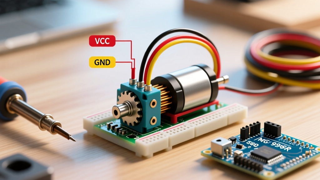
- Red Wire (VCC): Connect to the Arduino 5V pin.
- Orange/Yellow Wire (Signal): Connect to a digital pin (we will use Pin 9 in our code example).
Scenario B: Wiring a High-Torque Servo (MG996R)
For high-torque servos, or if you are daisy-chaining multiple micro servos, you must use an external power supply. A 5V 3A buck converter (like the LM2596 module) or a dedicated BEC (Battery Eliminator Circuit) is required.
- External Power GND: Connect to the negative rail of your breadboard or terminal block.
- External Power VCC (5V-6V): Connect to the positive rail.
- Servo Brown (GND): Connect to the negative rail.
- Servo Red (VCC): Connect to the positive rail.
- Servo Signal: Connect to Arduino Pin 9.
- The Common Ground Rule: You must run a jumper wire from the Arduino's GND pin to the external power supply's negative rail. Without this shared ground reference, the Arduino's PWM signal will float, causing the servo to twitch violently or ignore commands entirely.
Writing the Arduino Code: Beyond the Basics
Arduino controls servos using pulse-width modulation (PWM) at a 50Hz frequency. This means the microcontroller sends a pulse every 20 milliseconds. The width of that pulse (typically between 1000µs and 2000µs) dictates the shaft angle. According to the Arduino Servo Library Reference, the built-in library abstracts this timing into simple degree commands.
Standard Sweep and Position Code
#include <Servo.h>

// Create servo object
Servo myServo;

void setup() {
  // Attach the servo to Pin 9
  // Note: Servo.h uses Timer1 on Uno, disabling PWM on pins 9 & 10
  myServo.attach(9, 500, 2400);

  // Optional: Detach after moving to prevent continuous power draw and jitter
}

void loop() {
  // Move to specific angles
  myServo.write(0);   // Full counter-clockwise
  delay(1500);        // Wait for servo to reach position

  myServo.write(90);  // Center position
  delay(1500);

  myServo.write(180); // Full clockwise
  delay(1500);

  // Power-saving technique: detach when static
  myServo.detach();
  delay(5000);

  // Re-attach before next movement cycle
  myServo.attach(9, 500, 2400);
}
The Hidden Timer1 Conflict (Expert Insight)
Most beginner tutorials simply tell you to use the Servo.h library without explaining its hardware footprint. On the ATmega328P (Arduino Uno/Nano), the Servo library hijacks Timer1 to generate the precise 50Hz pulses. Because Timer1 also controls the hardware PWM for Pins 9 and 10, you lose the ability to use analogWrite() on those specific pins while the Servo library is active. If your project requires a DC motor via PWM and a servo simultaneously, attach the servo to Pin 6 or Pin 11, and reserve Pins 9 and 10 for your motor driver.
For sub-degree precision, avoid the standard write(angle) function. Instead, use writeMicroseconds(uS). As detailed in the Pololu RC Servo Motor Guide, mapping your sensor inputs directly to microsecond pulses (e.g., myServo.writeMicroseconds(1450)) eliminates the internal rounding errors that cause micro-stuttering in robotic arms.
Troubleshooting Common Servo Failure Modes
Even with correct wiring, environmental and electrical noise can cause erratic behavior. Use this diagnostic checklist to solve common issues:
1. The Servo Jitters or Twitches Randomly
- Cause: Voltage sag on the 5V rail due to the servo's initial inrush current, or electromagnetic interference (EMI) on the signal wire.
- Solution: Solder a 470µF to 1000µF electrolytic capacitor directly across the VCC and GND wires as close to the servo connector as possible. This acts as a local energy reservoir, smoothing out voltage dips. Ensure your signal wire is not routed parallel to high-current motor wires.
2. The Arduino Resets When the Servo Moves
- Cause: Brownout. The servo is pulling too much current from the Arduino's onboard regulator, dropping the system voltage below the ATmega328P's minimum operating threshold (usually around 4.5V for 16MHz operation).
- Solution: Switch to Scenario B (External Power). Ensure your external buck converter is rated for at least 3A continuous output. If using a USB power bank to power the Arduino, ensure the bank supports 'always-on' low-current modes, as some banks shut off if the Arduino's draw drops too low when the servo is detached.
3. The Servo Hums but Does Not Move
- Cause: Mechanical binding or insufficient starting torque. The internal potentiometer is trying to reach the target angle, but the load is too heavy, causing the motor to stall.
- Solution: Disconnect the mechanical load and test the servo bare. If it moves, your mechanical linkage is binding, or you need to upgrade to a higher-torque model (like a 20kg-cm DS3218). Prolonged stalling will burn out the internal DC motor windings within minutes.
Next Steps in Peripheral Interfacing
Mastering how to connect a servo to an Arduino opens the door to complex kinematics. Once you have stable power and jitter-free signal control, explore inverse kinematics libraries for multi-joint robotic arms, or integrate a PCA9685 16-channel I2C PWM driver board. The PCA9685 offloads the 50Hz pulse generation from the Arduino's timers entirely, allowing you to drive up to 16 high-torque servos without sacrificing a single hardware timer or PWM pin on your microcontroller. For further reading on I2C peripheral expansion, consult the Arduino Built-In Libraries Documentation to understand how hardware abstraction layers manage multiple simultaneous outputs.