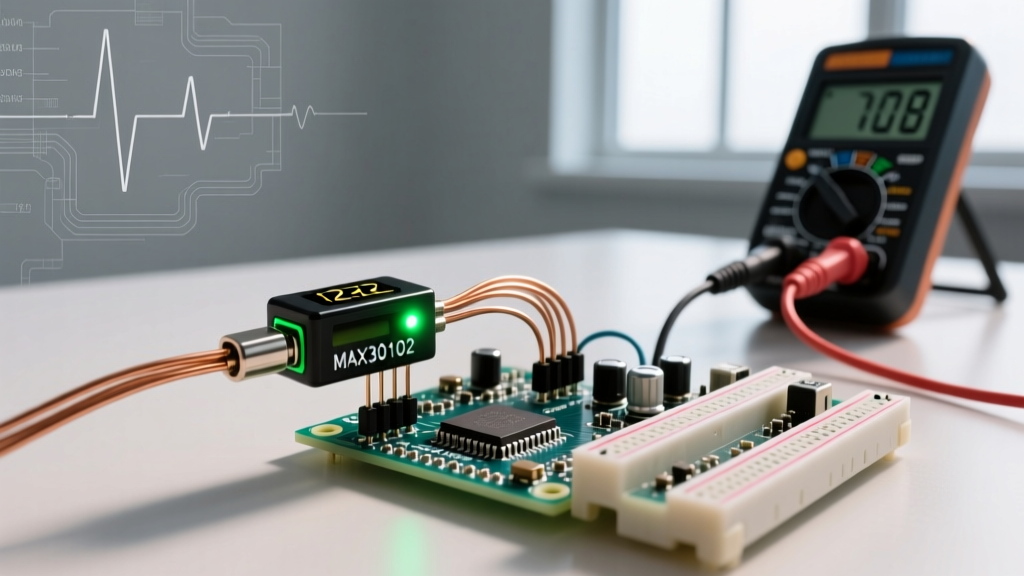

The Reality of Arduino Heartbeat Sensor Integration
Integrating an Arduino heartbeat sensor into a DIY biometric project often starts with excitement and ends in frustration. Photoplethysmography (PPG)—the optical technique used to detect blood volume changes in the microvascular bed of tissue—is notoriously sensitive to ambient light, motion artifacts, and electrical noise. Whether you are building a wearable fitness tracker or a desktop biometric lock, erratic pulse readings are the most common point of failure.
In 2026, the market is flooded with both high-fidelity digital I2C modules and ultra-cheap analog clones. Troubleshooting requires a fundamental understanding of which hardware architecture you are actually using. This guide bypasses generic advice and dives deep into component-level diagnostics, signal processing realities, and hardware-specific failure modes for the two most popular sensor families: analog PPG modules and the MAX30102 digital sensor.
Hardware Identification: Know Your Sensor Architecture
Before touching a single line of code, you must identify your exact hardware. The troubleshooting steps for an analog envelope detector are completely different from those for a digital I2C oximeter. Review the comparison matrix below to identify your module.
| Module Type | Core IC / Architecture | Interface | Typical 2026 Price | Primary Failure Mode |
|---|---|---|---|---|
| Genuine PulseSensor Amped | MCP6001 Op-Amp + APDS-9008 | Analog (0-5V) | $24.99 | Op-amp saturation from ambient 60Hz light |
| Generic KY-039 Clone | LM393 Comparator + Raw Photodiode | Digital (Square Wave) | $1.50 - $2.50 | False triggers from micro-movements; no analog envelope |
| SparkFun MAX30102 Breakout | MAX30102 (with Logic Shifters) | I2C (0x57) | $15.00 - $19.00 | Finger pressure artifacts; LED thermal throttling |
| Bare MAX30102 Module | MAX30102 (No Logic Translation) | I2C (1.8V Logic) | $3.00 - $5.00 | I2C bus lockup; fried SDA/SCL pins from 5V logic |
Troubleshooting Analog Sensors (PulseSensor & KY-039)
Analog heartbeat sensors output a continuous voltage waveform that represents the AC (pulsatile) and DC (baseline tissue) components of blood flow. If your Arduino Serial Plotter shows a flatline, a maxed-out 1023 ADC reading, or chaotic spikes, follow these targeted diagnostics.
Symptom: Flatline at 512 or Maxed at 1023/0
The Root Cause: Op-amp saturation or DC bias failure. Genuine PulseSensor modules use an MCP6001 operational amplifier to bias the signal at VCC/2 (approx 2.5V). If the ambient light is too intense (e.g., direct sunlight or 60Hz fluorescent tubes), the photodiode conducts heavily, pulling the op-amp output to the positive or negative rail.
The Fix:
- Optical Isolation: Wrap the sensor and the user's fingertip in opaque electrical tape or a 3D-printed TPU shroud. The sensor must operate in complete darkness to reject ambient 50/60Hz mains flicker.
- Verify the Bias Voltage: Use a multimeter to measure the sensor's SIG pin with no finger attached. It should read exactly half of your Arduino's logic voltage (2.5V for a 5V Uno, 1.65V for a 3.3V ESP32). If it reads 0V or 5V, the internal biasing resistors (typically 10kΩ and 10kΩ divider) are damaged or the op-amp is dead.
Symptom: The 'KY-039 Clone' Misunderstanding
Expert Warning: Over 70% of beginners buy the $2 KY-039 module expecting an analog waveform. The KY-039 does not output an analog wave. It uses an LM393 voltage comparator to output a digital 5V square wave every time it detects a threshold change. You cannot use standard analog peak-detection code with this module.
The Fix: If you are using a KY-039, you must use hardware interrupts (`attachInterrupt()`) on the Arduino to measure the time between falling edges of the digital square wave. Calculate BPM using the formula: BPM = 60000 / (pulse_interval_ms). Do not attempt to read it with `analogRead()`.
Troubleshooting Digital I2C Sensors (MAX30102 / MAX30105)
The MAX30102 is the industry standard for Arduino-based SpO2 and heart rate monitoring. However, bare modules imported from overseas marketplaces frequently cause severe hardware lockups due to logic-level mismatches.
Symptom: I2C Scanner Finds Nothing or Hangs Indefinitely
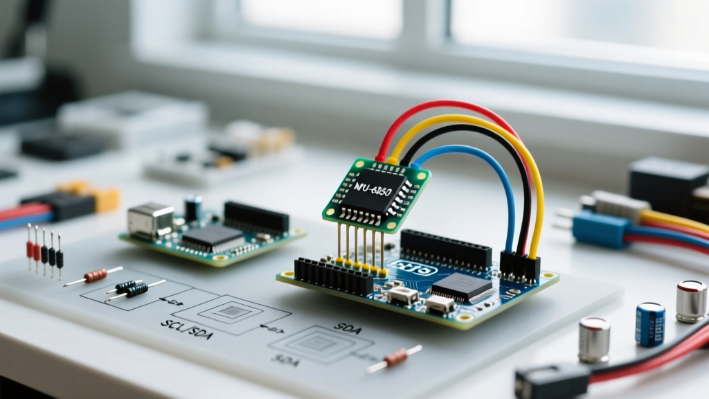
The Root Cause: The MAX30102 chip operates internally at 1.8V. Its SDA and SCL pins are not 5V tolerant. If you connect a bare module directly to a 5V Arduino Uno without a logic level shifter, you will permanently damage the I2C transceiver inside the IC. Furthermore, the I2C bus requires pull-up resistors, which many cheap $3 modules omit.
The Fix:
- Check Pull-Up Resistors: Measure the resistance between SDA/SCL and VCC (3.3V). You should see approximately 4.7kΩ. If the multimeter reads infinite (OL), solder 4.7kΩ surface-mount or through-hole resistors to the SDA and SCL lines.
- Implement Logic Translation: If you are using a 5V microcontroller, you must use a BSS138 bidirectional logic level converter. Connect the 3.3V side to the sensor and the 5V side to the Arduino. Refer to the Arduino Wire library documentation for proper I2C bus wiring topologies.
- Verify Power Delivery: The MAX30102 can draw up to 1.2mA for the IC, but the internal IR/Red LEDs can draw up to 50mA each during peak pulses. Powering the module via the Arduino's 3.3V regulator (which often maxes out at 50mA-150mA) causes brownouts. Power the VCC pin from an external 3.3V LDO (like an AMS1117-3.3) capable of delivering 300mA+.
Symptom: SpO2 and BPM Algorithms Output Nonsense (e.g., 255 BPM or -1%)
The Root Cause: The Analog Devices MAX30102 datasheet specifies that accurate SpO2 calculation requires a precise ratio of the AC to DC components of both the Red (660nm) and IR (880nm) LEDs. If the sensor is strapped too tightly, the tissue compresses, collapsing the capillaries and destroying the AC pulsatile signal. If strapped too loosely, motion artifacts overwhelm the photodiode.
The Fix:
- Adjust LED Current: In your initialization code, reduce the LED pulse amplitude. Start with
0x1F(approx 6.4mA) instead of the default0xFF(50mA). Lower current reduces thermal noise and prevents tissue compression artifacts. - Set the Correct Sampling Rate: Human heart rates range from 40 to 200 BPM (0.66 Hz to 3.33 Hz). According to the Nyquist-Shannon sampling theorem, you need a minimum sampling rate of 7 Hz. However, for the onboard FIFO buffer to function correctly without aliasing, configure the sensor to sample at 50 Hz or 100 Hz with an ADC resolution of 18 bits.
Code-Level Diagnostics: Escaping the Delay() Trap
The most insidious cause of erratic heartbeat data is poor firmware timing. PPG signal processing requires strict, deterministic sampling intervals. If your Arduino code uses delay() or relies on the execution time of Serial.print() to space out readings, your sampling frequency will jitter, completely destroying the Fast Fourier Transform (FFT) or bandpass filters used to extract the heart rate.
The Hardware Interrupt Solution
To achieve a rock-solid 50Hz sampling rate, abandon the main loop() for data acquisition. Use the TimerOne library to trigger an Interrupt Service Routine (ISR).
#include <TimerOne.h>

volatile bool sampleReady = false;

void setup() {
  // Initialize sensor via I2C...
  Timer1.initialize(20000); // 20,000 microseconds = 50Hz
  Timer1.attachInterrupt(readSensorISR);
}

void readSensorISR() {
  sampleReady = true; // Set flag, do NOT read I2C inside ISR
}

void loop() {
  if (sampleReady) {
    sampleReady = false;
    // Read I2C FIFO, apply moving average, calculate BPM
  }
}
Crucial Rule: Never execute I2C wire readings or heavy math inside the ISR itself. The ISR should only set a boolean flag. The main loop handles the heavy lifting when the flag is true. This prevents I2C bus timeouts and Watchdog Timer resets.
Expert Diagnostic Decision Tree
When your Arduino heartbeat sensor fails, follow this exact sequence to isolate the fault domain:
- Step 1: The I2C Scanner Test. Run the standard Arduino I2C Scanner sketch. If the sensor does not report
0x57, the fault is strictly hardware (wiring, pull-ups, or dead IC). Stop writing application code until this passes. - Step 2: The Raw Data Dump. Bypass all BPM algorithms. Stream the raw ADC values (analog) or raw FIFO IR/Red values (digital) to the Serial Plotter at 115200 baud.
- Step 3: The Visual Inspection. Look at the Serial Plotter. Do you see a clean sine-like wave with a period of roughly 0.8 to 1.2 seconds?
- If YES: Your hardware is perfect. Your BPM algorithm (peak detection or FFT) is flawed. Implement a 0.5Hz - 5.0Hz digital bandpass filter.
- If NO (Sawtooth/Chaotic): You have 50/60Hz mains interference. Move away from AC-powered desktop lamps and switch the Arduino to battery power to eliminate USB ground loops.
- If NO (Flatline): The photodiode is saturated or dead. Check optical sealing and LED current settings.
Final Thoughts on Biometric Reliability
Troubleshooting an Arduino heartbeat sensor is rarely about replacing the component; it is about managing the physical and electrical environment in which the component operates. By understanding the distinction between analog envelope detectors and digital I2C oximeters, enforcing strict timing via hardware interrupts, and mitigating optical noise, you can elevate a $3 DIY module from a frustrating toy into a reliable biometric instrument.