
When integrating an Arduino LED screen into a custom electronics project, achieving true-to-life color accuracy and uniform brightness is rarely a plug-and-play experience. Whether you are driving a 16x16 WS2812B addressable RGB matrix for a custom synthesizer interface or wiring a 2.8-inch ILI9341 TFT LCD for a sensor dashboard, out-of-the-box color rendering is often plagued by voltage drop, non-linear human vision, and factory gamma variances. In 2026, with high-speed microcontrollers like the ESP32-S3 and Raspberry Pi Pico 2 pushing higher refresh rates, understanding the physics of display calibration is essential for professional-grade results.
The Two Dominant Arduino LED Screen Architectures
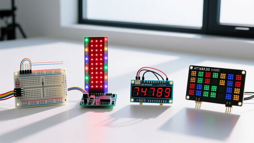
The term 'LED screen' in the maker and engineering community generally refers to two distinct peripheral categories. Calibration requires a fundamentally different approach for each:
| Feature | WS2812B / NeoPixel RGB Matrix | ILI9341 TFT LCD (LED Backlit) |
|---|---|---|
| Primary Use Case | Dynamic lighting, large-format pixel art, audio visualizers | Detailed sensor dashboards, GUIs, camera feeds |
| Typical 2026 Cost | $25 - $35 (16x16 Panel) | $12 - $18 (2.8-inch SPI Module) |
| Max Current Draw | ~15.3A (at full white, 256 pixels) | ~120mA (including LED backlight) |
| Core Calibration Need | Voltage drop mapping & White-point balancing | Gamma register tuning & SPI noise filtering |
WS2812B Matrix Calibration: Voltage & White Point
Addressable LED matrices suffer from two major accuracy killers: resistive voltage drop across the flexible printed circuit board (FPCB) and factory-level variations in the red, green, and blue diode dies. According to the Adafruit NeoPixel Überguide, pushing 60mA per pixel through thin copper traces guarantees that the last pixel in a 256-LED chain will receive significantly less than the required 5V.
Fixing the 5V Voltage Drop
If your Arduino LED screen exhibits a pink or yellow tint at the far edges of the matrix, you are witnessing voltage drop. The blue diode requires the highest forward voltage; when VCC drops below 4.2V, the blue channel fails first, leaving red and green dominant.
- Power Injection Rule: For a 16x16 matrix, inject 5V power using 18 AWG silicone wire at least every 4 rows (every 64 pixels).
- Measurement: Use a digital multimeter to probe the VCC and GND pads of the very last pixel in the data chain while displaying full white. It must read between 4.8V and 5.0V.
- Capacitor Buffering: Place a 1000µF, 6.3V electrolytic capacitor at the primary power injection point to handle transient current spikes during high-contrast scene changes.
White Point Balancing (The 255,255,255 Myth)
Sending an RGB value of (255, 255, 255) to a WS2812B matrix rarely produces a neutral white. Due to differing luminous efficacies of the internal semiconductor dies, the green channel is typically much brighter than the red and blue channels. To calibrate a true D65 white point (standard daylight), you must manually restrict the green and blue channels in your firmware. A common baseline calibration for generic 2026-manufactured WS2812B panels is (255, 180, 220). For precise scientific or medical instrument displays, use a hardware colorimeter to sample the CIE 1931 chromaticity coordinates and adjust the multipliers accordingly.
Expert Hardware Tip: If you are driving a 5V WS2812B LED screen with a 3.3V logic microcontroller (like the ESP32 or Arduino Due), you will experience erratic color shifting and flickering. The WS2812B datasheet requires a logic high of at least 0.7 x VCC (3.5V). Always route your data pin through a 74AHCT125 logic level shifter to guarantee a clean 5V data signal.
ILI9341 TFT Calibration: Gamma Registers
When your project requires an Arduino LED screen capable of rendering 65,536 colors (16-bit) for detailed graphs or images, the ILI9341 TFT LCD is the industry standard. However, factory-default gamma curves often result in crushed blacks and blown-out highlights. The ILI9341 controller allows direct manipulation of its internal gamma registers via SPI commands.
Modifying the E0 and E1 Registers
The ILI9341 uses two 15-byte arrays to define the Positive Gamma Correction (0xE0) and Negative Gamma Correction (0xE1) curves. By adjusting these hex values in your initialization sequence, you can linearize the display's output to match the W3C sRGB Color Space Specification.
Instead of relying on the generic initialization code provided in standard Arduino GFX libraries, implement a custom calibration array. A widely tested configuration for improved shadow detail and color vibrancy on 2.4-inch and 2.8-inch ILI9341 modules is:
- Positive Gamma (0xE0):
0x0F, 0x31, 0x2B, 0x0C, 0x0E, 0x08, 0x4E, 0xF1, 0x37, 0x07, 0x10, 0x03, 0x0E, 0x09, 0x00 - Negative Gamma (0xE1):
0x00, 0x0E, 0x14, 0x03, 0x11, 0x07, 0x31, 0xC1, 0x48, 0x08, 0x0F, 0x0C, 0x31, 0x36, 0x0F
Flashing these registers via the tft.pushCommand() function in the TFT_eSPI library dramatically reduces the 'washed out' look common to budget TFT peripherals.
Software-Side Gamma Correction with FastLED
Even with perfect hardware power injection and white-point balancing, an Arduino LED screen will appear to have abrupt, stepped transitions at low brightness levels. This is because human vision is logarithmic, while PWM (Pulse Width Modulation) is linear. To achieve smooth, accurate fades, you must apply gamma correction in software.
The FastLED Documentation provides built-in utilities to handle this math. Instead of writing raw values to the LED array, use the apply_gamma_video() function. This maps your linear 0-255 input to a perceptually uniform output curve, ensuring that a 10% increase in code value translates to a perceived 10% increase in brightness by the human eye. This is critical for applications like PWM-driven backlight dimming or smooth ambient lighting transitions.
Troubleshooting Common Calibration Failures
When your display accuracy degrades, use this diagnostic checklist to isolate the failure mode:
1. High-Frequency Flickering on WS2812B Panels
Cause: Data line noise or insufficient grounding. Solution: Ensure the ground wire from your microcontroller is tied directly to the ground plane of the LED matrix, not just the power supply ground. Add a 470-ohm resistor in series with the data line, placed as close to the first pixel's DIN pad as possible to prevent signal ringing.
2. ILI9341 Screen Tearing During Fast Sensor Updates
Cause: SPI bus clock speed mismatch or lack of VSYNC. Solution: Cap your SPI frequency at 40MHz for standard jumper-wire connections. If using a custom PCB with short, impedance-matched traces, you can push the ILI9341 to 80MHz. Implement double-buffering in your code to draw the next frame in RAM while the current frame is being scanned out to the display.
3. Color Shifting When Displaying Deep Reds
Cause: Power supply sag. The red diode in a WS2812B draws the most current when fully saturated. Solution: Upgrade your bench power supply or switching buck converter. A 16x16 matrix displaying pure red can pull upwards of 12A transiently. Use a power supply rated for at least 20A continuous to maintain voltage regulation.
Calibrating an Arduino LED screen is a multidisciplinary task that bridges electrical engineering, optics, and firmware development. By addressing voltage drop, applying perceptual gamma correction, and tuning hardware registers, you can elevate a basic hobbyist display into a precision instrument interface.