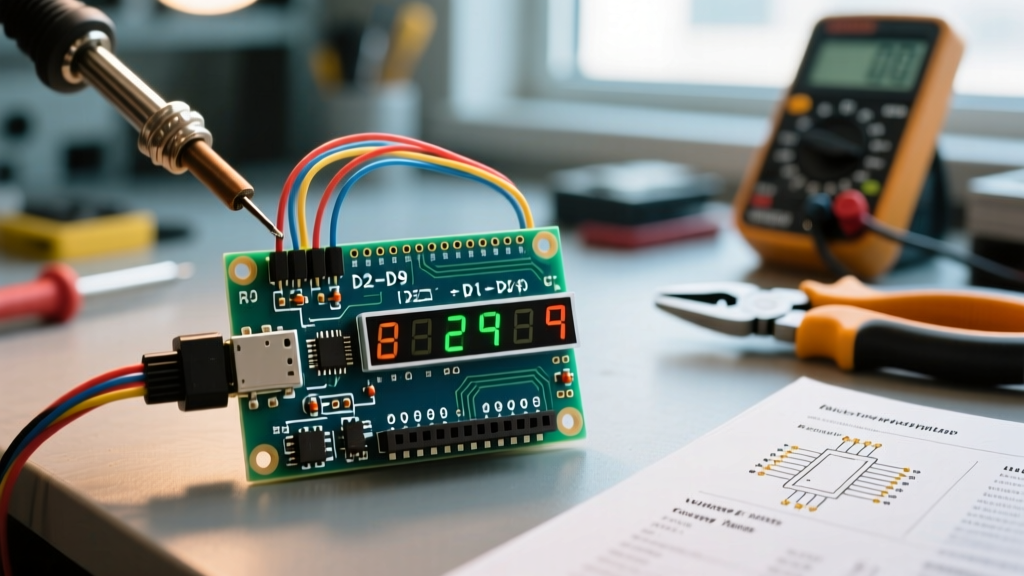

Decoding the Datasheet: Your Blueprint for Display Integration
When hobbyists and engineers begin prototyping digital readouts, the combination of an Arduino and seven segment display remains one of the most reliable, high-visibility, and cost-effective choices available in 2026. While OLED and TFT screens have dropped in price, standard 7-segment LEDs (like the ubiquitous Kingbright SC56-11GWA or Lite-On LTC-4727JR) still dominate industrial panels, automotive dashboards, and DIY计分boards due to their extreme brightness and wide viewing angles. However, blindly wiring these displays to microcontroller pins without consulting the manufacturer's datasheet is a primary cause of burnt-out GPIO ports and dim, flickering outputs.
This guide acts as a datasheet explainer, translating the dense electrical characteristics, absolute maximum ratings, and optical specifications found in standard LED datasheets into actionable wiring strategies for Arduino Uno, Nano, and Mega boards.
Key Datasheet Parameters Decoded
Before touching a breadboard, you must understand the difference between Absolute Maximum Ratings and Recommended Operating Conditions. The absolute maximums are stress ratings; operating at these levels will degrade the display's lifespan or instantly destroy the silicon die inside the LED package.
Absolute Maximums vs. Recommended Operating Conditions
| Parameter | Absolute Maximum | Recommended Operating | Engineering Context |
|---|---|---|---|
| Forward Current ($I_f$) per segment | 30 mA | 10 mA to 15 mA | Continuous 30 mA causes thermal runaway and rapid luminance decay. |
| Peak Forward Current ($I_{peak}$) | 100 mA (1/10 duty cycle) | 60 mA (multiplexed) | Applies only during high-speed multiplexing; never use for static DC drive. |
| Reverse Voltage ($V_r$) | 5 V | N/A | LEDs are diodes; reverse biasing beyond 5V causes avalanche breakdown. |
| Power Dissipation ($P_d$) | 100 mW per segment | 30 mW to 45 mW | Exceeding this melts the internal gold wire bonds. |
Pinout Anatomy: Common Anode vs. Common Cathode
The most critical page in any 7-segment display tutorial or datasheet is the mechanical drawing and pinout diagram. A standard single-digit display features 10 pins. Pins 3 and 8 are internally connected and serve as the 'Common' pin. The physical orientation is dictated by a small bevel on the bottom edge or a dot next to Pin 1.
Identifying Your Display Type
- Common Cathode (CC): The common pins connect to Ground (GND). The Arduino GPIO pins must output HIGH (5V) through current-limiting resistors to illuminate specific segments (a, b, c, d, e, f, g, dp).
- Common Anode (CA): The common pins connect to the positive supply (5V). The Arduino GPIO pins must sink current by outputting LOW (0V) to complete the circuit and illuminate the segments.
The 'Ghosting' Failure Mode: If you wire a Common Anode display using code written for a Common Cathode display, the logic will be inverted. Worse, if you attempt to drive a Common Anode display by sourcing current from the Arduino pins to the common pin, you will exceed the ATmega328P's total port current limit, potentially bricking the microcontroller.
Current Limiting: The Math Behind the Resistors
Datasheets specify the Forward Voltage ($V_f$), which varies by the semiconductor material used to create the LED color. In 2026, you will typically encounter Aluminum Gallium Arsenide (AlGaAs) for ultra-bright red, and Indium Gallium Nitride (InGaN) for blue or white displays.
Calculating the Series Resistor
Never connect an Arduino GPIO directly to a 7-segment LED without a resistor. The ATmega328P GPIO pins have an absolute maximum current rating of 40 mA, but Microchip's official specifications strongly recommend keeping continuous current at or below 20 mA to ensure long-term reliability. Furthermore, the total current sourced or sunk by a single port (e.g., Port D, which handles pins 0-7) must not exceed 100 mA.
Use Ohm's Law: $R = (V_{cc} - V_f) / I_f$
- Identify $V_{cc}$: Standard Arduino Uno operates at 5.0V.
- Identify $V_f$: A standard red display (like the Kingbright SC56-11GWA) has a typical $V_f$ of 1.8V to 2.2V. Let us use 2.0V.
- Select $I_f$: Target a safe continuous current of 15 mA (0.015 A).
- Calculate: $R = (5.0 - 2.0) / 0.015 = 200 \Omega$.
Since 200Ω is not a standard E12 series resistor value, round up to the nearest standard value: 220Ω. For blue or white displays with a $V_f$ of 3.2V, the calculation yields $R = (5.0 - 3.2) / 0.015 = 120 \Omega$. Using a 150Ω resistor ensures safe operation.
Multiplexing and Peak Current Ratings
When your project requires a 4-digit display module, wiring 32 individual segment pins to an Arduino is impossible without expansion hardware. This is where multiplexing comes into play, leveraging the datasheet's 'Peak Forward Current' specification and the human eye's Persistence of Vision (POV).
How Multiplexing Exploits the Datasheet
In a multiplexed setup, all 'a' segments across the four digits are tied together, all 'b' segments are tied together, and so on. The Arduino activates only one common digit pin at a time, cycling through them rapidly. If the refresh rate exceeds 60Hz (ideally 100Hz+), the human brain perceives all four digits as being lit simultaneously.
Because each LED segment is only turned on for 25% of the time (a 1/4 duty cycle on a 4-digit display), the datasheet allows you to drive the LEDs with a higher peak current during their active window to maintain perceived brightness. However, you must use external NPN (e.g., 2N3904) or PNP (e.g., 2N3906) transistors to switch the common digit pins, as the combined current of 8 segments at 15mA each equals 120mA—far exceeding the Arduino's 40mA per-pin limit.
Real-World Integration: Shift Registers vs. Direct Drive
When integrating an Arduino and seven segment display system, managing pin count is a major architectural decision. Below is a comparison of the two most common integration topologies.
Topology Comparison Matrix
| Feature | Direct GPIO Drive (Single Digit) | 74HC595 Shift Register (Multi-Digit) | TM1637 Dedicated Driver IC |
|---|---|---|---|
| Arduino Pins Required | 8 (or 9 with decimal point) | 3 (Data, Clock, Latch) | 2 (CLK, DIO) |
| Hardware Complexity | Low (Just resistors) | Medium (Requires IC, bypass caps, transistors) | Very Low (Integrated module) |
| CPU Overhead | Minimal (Direct PORT manipulation) | Moderate (Requires bit-banging or SPI) | Low (I2C-like protocol handles multiplexing) |
| Best Use Case | Simple status indicators, single counters | Custom PCBs, high-brightness industrial panels | Breadboard prototyping, clock/timer projects |
Pro-Tip: Using Shift Registers for Scalability
If you are designing a custom PCB in 2026 and want to drive multiple digits without burdening the ATmega328P, cascading 74HC595 shift registers is the professional standard. As detailed in the Arduino ShiftOut Guide, you can send an 8-bit byte representing the segment states, and the shift register handles the current sinking/sourcing (up to 35mA per pin on the 74HC595, though 20mA is safer). This frees up the microcontroller to handle sensor polling and wireless communication without display flickering interrupting the main loop.
Summary and Best Practices
Successfully pairing an Arduino and seven segment display requires respecting the physics outlined in the component datasheet. Always verify whether your display is Common Anode or Common Cathode before applying power. Calculate your current-limiting resistors based on the specific forward voltage of the LED color, not a generic assumption. Finally, when scaling beyond a single digit, abandon direct GPIO wiring in favor of transistor-switched multiplexing or dedicated driver ICs to protect your microcontroller from overcurrent failures. By treating the datasheet as an engineering blueprint rather than a suggestion, your digital readouts will remain bright, stable, and electrically safe for years to come.