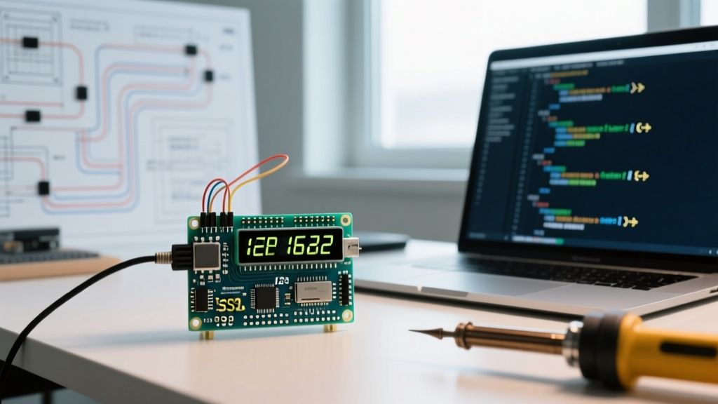

The Hidden Bottleneck in Sensor Calibration Interfaces
When engineers and hobbyists build custom sensor arrays—whether for environmental monitoring, precision load cells, or pH metering—the focus is overwhelmingly placed on ADC resolution and signal conditioning. Yet, the final and most critical step in the calibration process relies on the Human-Machine Interface (HMI). If your display flickers, truncates decimal places, or suffers from I2C bus latency, accurate calibration becomes impossible. Writing robust, precision-oriented code for LCD Arduino setups is not just about printing text; it is about creating a stable, real-time visual feedback loop that allows for micro-adjustments during the calibration phase.
In this guide, we dissect the architecture of calibration-grade LCD interfaces. We will move beyond basic lcd.print() tutorials and explore memory-safe float rendering, flicker-elimination algorithms, and I2C bus optimization for HD44780-based displays equipped with PCF8574T backpacks.
Hardware Baseline: I2C Backpacks and Contrast Tuning
Before writing a single line of firmware, the physical layer must be optimized for readability. The standard 1602 and 2004 LCD modules utilizing the HD44780 controller remain the industry standard for low-cost calibration jigs. As of 2026, a high-quality 1602 display with an integrated PCF8574T I2C backpack costs between $3.50 and $5.00, making it an economical choice for multi-node calibration benches.
The V0 Contrast Voltage Threshold
Accuracy in calibration requires absolute visual clarity. The V0 (contrast) pin on the LCD backpack dictates the liquid crystal alignment. While many tutorials suggest using a 10kΩ trim potentiometer, professional calibration rigs hardcode this voltage to eliminate physical drift caused by vibration and temperature fluctuations.
- Optimal Voltage at 25°C: 0.45V to 0.65V (yields the highest contrast ratio without ghosting).
- Optimal Voltage at 40°C: 0.30V to 0.45V (liquid crystals become more sensitive to heat).
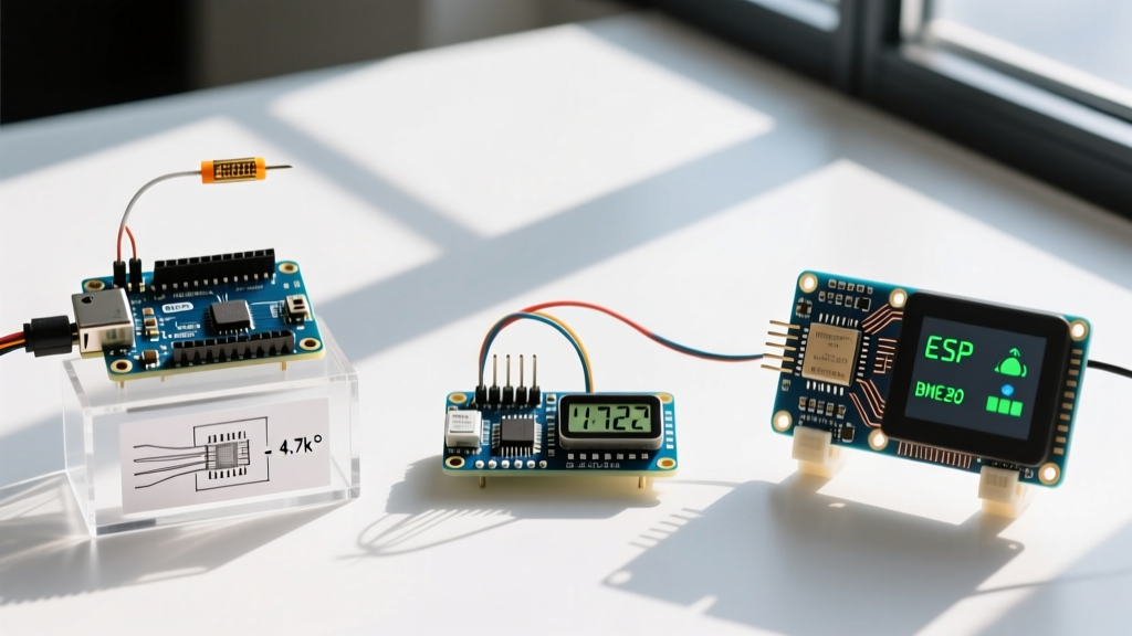
Instead of a potentiometer, use a simple voltage divider with 1% tolerance metal film resistors (e.g., a 4.7kΩ pull-up and a 1kΩ pull-down from the 5V rail) to lock the V0 pin at precisely 0.87V, or utilize a PWM pin filtered with a 10μF capacitor to allow software-defined contrast adjustment during thermal chamber testing.
Architecting Flicker-Free Code for LCD Arduino Setups
The most common failure mode in DIY calibration interfaces is screen flicker. This occurs when developers use lcd.clear() inside the main loop() before updating sensor values. According to the official Arduino LiquidCrystal library documentation, the clear() command takes approximately 1.52 milliseconds to execute because it must write zeros to all 80 bytes of the display's DDRAM. When executed at 50Hz, this creates a perceptible strobe effect that induces eye strain and makes reading fluctuating millivolt outputs impossible.
The Selective Overwrite Strategy
To achieve a rock-solid display, you must abandon lcd.clear() for dynamic data. Instead, use targeted cursor positioning and space-padding to overwrite only the characters that change.
// BAD: Causes 1.52ms flicker and bus blocking
lcd.clear();
lcd.setCursor(0, 1);
lcd.print("Voltage: ");
lcd.print(sensorValue);

// GOOD: Zero-flicker selective overwrite
lcd.setCursor(9, 1); // Target only the data field
if (sensorValue < 10.0) lcd.print(" "); // Pad with space if dropping a digit
lcd.print(sensorValue);
By targeting specific DDRAM addresses, character updates drop to roughly 400 microseconds per character, completely eliminating visual tearing and freeing up the I2C bus for high-priority sensor polling.
Handling Floating-Point Precision Without Heap Fragmentation
Calibration demands exact decimal representation. A pH sensor reading of 7.00 is fundamentally different from 7.0 in a laboratory context. However, using the standard Arduino String class to format floats dynamically allocates memory on the heap. Over a 48-hour calibration burn-in, this leads to heap fragmentation, resulting in memory leaks, system crashes, and corrupted I2C transmissions.
Expert Insight: Never use the
Stringobject for continuous LCD updates in calibration firmware. Always rely on C-style character arrays and pointer arithmetic to maintain deterministic memory usage.
Implementing dtostrf() for Deterministic Rendering
The dtostrf() function converts a double/float to a C-string with strict control over width and precision, utilizing a pre-allocated static buffer. This guarantees zero heap fragmentation.
char lcdBuffer[16];
// Convert float to string: [value], [min_width], [precision], [buffer]
dtostrf(calibratedSensorValue, 6, 3, lcdBuffer);

lcd.setCursor(8, 0);
lcd.print(lcdBuffer);
This ensures that a value like 4.2 is rendered as 4.200 (with leading spaces), maintaining column alignment and preventing leftover characters from previous, longer readings from lingering on the screen.
Update Strategy Comparison Matrix
Choosing the right rendering strategy depends on your sensor's sampling rate and the microcontroller's I2C clock speed. Below is a comparison of rendering techniques for a standard 16x2 LCD running at 400kHz I2C.
| Rendering Strategy | Execution Time (approx) | Visual Flicker | Heap Impact | Best Use Case |
|---|---|---|---|---|
lcd.clear() + Print |
~2.8 ms | Severe | Low | Static menu transitions only |
| Selective Overwrite (Float) | ~0.6 ms | None | Low | Real-time sensor telemetry |
| String Object Concatenation | ~1.2 ms (varies) | Mild | High (Fragmentation) | Avoid entirely in production |
| Custom Frame Buffer (I2C) | ~3.5 ms (bulk write) | None (VSYNC) | Medium (Static Array) | Complex graphical UI / Bar graphs |
Building the Calibration State Machine
A professional calibration interface requires more than just displaying data; it requires a state machine to handle zero-offset adjustments, span calibration, and EEPROM saving. When writing your code for LCD Arduino calibration menus, structure your UI logic using an enum based state machine rather than blocking delay() calls.
Non-Blocking Menu Logic
Using delay() halts the ADC sampling loop, which can cause the sensor to drift during the calibration hold period. Implement a millis() based UI refresh timer that runs independently of the sensor polling rate.
enum CalState { STATE_LIVE_READ, STATE_ZERO_CAL, STATE_SPAN_CAL, STATE_SAVE };
CalState currentUIState = STATE_LIVE_READ;

unsigned long lastUIRefresh = 0;
const int UI_REFRESH_INTERVAL = 100; // 10Hz UI update rate

void loop() {
  // 1. Poll sensor at 1000Hz (non-blocking)
  readSensorADC();

  // 2. Update LCD at 10Hz (non-blocking)
  if (millis() - lastUIRefresh >= UI_REFRESH_INTERVAL) {
    lastUIRefresh = millis();
    updateLCDDisplay(currentUIState);
  }

  // 3. Handle button inputs for state transitions
  processCalibrationButtons();
}
This architecture ensures that the sensor data is continuously averaged in the background, while the LCD updates at a steady 10 frames per second—fast enough to appear real-time to the human eye, but slow enough to prevent I2C bus saturation.
Edge Cases: I2C Capacitance and Ghosting
When integrating LCDs into larger calibration rigs with long cable runs, I2C bus capacitance becomes a critical failure point. The Texas Instruments PCF8574 datasheet specifies a maximum bus capacitance of 400pF. If your ribbon cable exceeds 30cm, the capacitance will round off the I2C square waves, leading to missed ACK bits and 'ghost' characters appearing on the LCD.
Hardware and Software Mitigations
- Pull-Up Resistor Tuning: The standard 10kΩ pull-up resistors on cheap LCD backpacks are too weak for high-speed or high-capacitance buses. Replace them with 4.7kΩ or even 2.2kΩ resistors to sharpen the signal rise times.
- I2C Clock Adjustment: If long cables are unavoidable, drop the I2C clock speed in your setup function to ensure signal integrity:
Wire.setClock(100000);. - Ghosting Clear Routine: If the LCD exhibits stuck pixels due to EMI from nearby relay modules, implement a background 'clear and rewrite' routine that triggers once every 60 seconds to flush the DDRAM without interrupting the user's visual flow.
Summary: Precision is in the Details
Writing calibration-grade firmware requires treating the display not as an afterthought, but as a critical measurement instrument. By eliminating lcd.clear() flicker, enforcing strict memory management with dtostrf(), and respecting the electrical limits of the I2C bus, you transform a basic hobbyist screen into a reliable, laboratory-grade calibration interface. For further reading on I2C integration and backpack wiring, the Adafruit I2C/SPI LCD Backpack guide provides excellent foundational schematics that complement the advanced software techniques detailed here.