
The 64:1 Gearbox Myth: Why Your Arduino 28BYJ-48 Stepper Motor Drifts
If you have ever built a pan-tilt camera mount, a DIY CNC plotter, or an automated blind controller using the ubiquitous Arduino 28BYJ-48 stepper motor, you have likely encountered cumulative positional drift. You command the motor to rotate exactly 360 degrees, but after 50 revolutions, your end-effector is off by several degrees. In 2026, while high-end NEMA 17 closed-loop steppers dominate industrial automation, the 28BYJ-48 remains the undisputed king of budget DIY prototyping, costing roughly $4.50 to $6.00 for a motor and ULN2003 driver board kit. However, achieving true precision requires moving beyond the default library constants and understanding the mechanical realities of this specific peripheral.
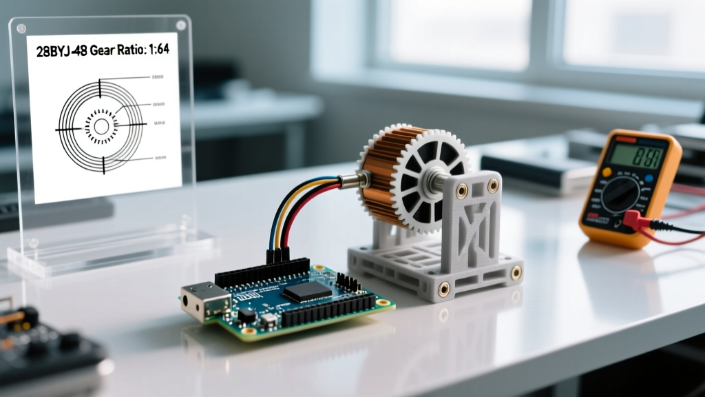
The root of the inaccuracy lies in a widely propagated myth: the internal gear reduction ratio. Almost every beginner tutorial and default Arduino Stepper library example assumes the 28BYJ-48 has a gear ratio of exactly 64:1. This is mathematically false. By reverse-engineering the internal 5-stage gear train, the actual ratio is derived from the following tooth counts: (32/9) × (22/11) × (26/9) × (31/10) × (32/9). This results in an exact gear reduction of 63.68395:1.
Expert Insight: The bare motor shaft requires 64 half-steps (or 32 full steps) to complete one revolution. Multiplying 64 half-steps by the true gear ratio of 63.68395 yields 4075.77 half-steps per output shaft revolution. If your code uses the standard 4096 constant, you are over-driving the motor by 20.23 steps per revolution. Over 100 rotations, this accumulates to an error of over 179 degrees—nearly half a full rotation!
Hardware Calibration: Voltage Drop and the ULN2003 Limitations
Before writing a single line of calibration code, you must address the physical drive circuit. The standard kit includes a ULN2003 Darlington transistor array. While cheap and robust enough to handle the 500mA peak current of the 28BYJ-48, the ULN2003 introduces a significant voltage drop.
The Vce(sat) Penalty
Each Darlington pair inside the ULN2003 has a collector-emitter saturation voltage (Vce(sat)) of approximately 1.0V to 1.5V depending on the load. If you power the board with a standard 5.0V USB supply, the motor coils are only receiving 3.5V to 4.0V. Because stepper motor torque is directly proportional to coil current (and thus voltage, per Ohm's law), this 20% voltage drop severely limits your low-speed torque and exacerbates missed steps during high-acceleration routines.
- Standard 5V Variant: Rated for 5V. Running it at 12V via the ULN2003 will double the torque and max RPM (up to ~25 RPM), but the ULN2003 will overheat and fail within minutes without a massive heatsink. The motor will also run hot (60°C+ casing temp).
- 12V Variant (Recommended for 2026 builds): Manufacturers now widely produce a native 12V version of the 28BYJ-48 (often with a blue or black cap instead of white). Using a 12V power supply with the 12V motor variant eliminates the thermal risk while providing the higher voltage headroom needed to overcome the ULN2003 voltage drop, yielding a much stiffer, more accurate hold.
Software Calibration: Correcting the AccelStepper Constants
To achieve sub-degree accuracy, abandon the default Arduino Stepper.h library. It blocks execution during movement and lacks acceleration profiling, which causes the 28BYJ-48 to stall and lose steps when starting or stopping abruptly. Instead, use Mike McCauley's AccelStepper library, which handles non-blocking acceleration ramps.
Setting the True Step Count
When initializing your AccelStepper object in HALF_STEP mode (which provides the smoothest operation for unipolar motors), set the steps-per-revolution constant to the mathematically verified value:
#include <AccelStepper.h>

// Define pins IN1, IN2, IN3, IN4 connected to ULN2003
AccelStepper stepper(AccelStepper::HALF4WIRE, 8, 10, 9, 11);

void setup() {
  // TRUE calibrated half-steps per revolution
  stepper.setMaxSpeed(1500.0);
  stepper.setAcceleration(800.0);

  // To move exactly 10 output shaft revolutions:
  // 10 revs * 4075.77 steps/rev = 40757.7 steps
  stepper.moveTo(40758);
}
By using 4075.77 (or rounding to 4076 for integer math, which introduces a negligible 0.005% error), your cumulative drift is effectively eliminated. For applications requiring absolute positional memory over thousands of rotations, implement a physical homing switch (like a micro limit switch or a Hall effect sensor) to reset the stepper.setCurrentPosition(0) parameter on boot.
Performance Matrix: 5V vs 12V Variants
Understanding the physical limits of your specific motor variant is critical for setting the setMaxSpeed() and setAcceleration() parameters. Pushing the motor beyond its electromechanical limits guarantees missed steps, ruining your calibration.
| Metric | 5V Variant (Standard) | 12V Variant (High-Torque) |
|---|---|---|
| Coil Resistance | ~50 Ω (per phase) | ~200 Ω (per phase) |
| Peak Current Draw | ~100mA - 160mA | ~60mA - 80mA |
| Hold Torque (at shaft) | ~34.3 mN·m (350 gf·cm) | ~45.0 mN·m (460 gf·cm) |
| Max Reliable RPM (No Load) | ~14 RPM | ~28 RPM |
| Optimal Acceleration (steps/s²) | 600 - 800 | 1200 - 1500 |
Advanced Calibration: Backlash and Microstepping
Even with perfect step math, the 28BYJ-48 suffers from mechanical backlash due to the tolerances in its plastic and sintered metal spur gears. When reversing direction, the motor shaft will turn slightly before the output shaft engages, typically resulting in 0.5° to 1.2° of dead zone.
Software Backlash Compensation
If your project involves bidirectional movement (e.g., a robotic arm joint), you must implement backlash compensation in your code. Create a wrapper function that adds a fixed number of 'phantom steps' whenever the direction of travel changes.
- Measure the backlash by attaching a laser pointer to the shaft and projecting it onto a wall 2 meters away.
- Command a direction change and count how many half-steps occur before the laser dot moves.
- For most 28BYJ-48 units, this value is between 12 and 18 half-steps.
- Add this constant to your target position only on direction reversals.
The Microstepping Reality Check
Can you microstep the 28BYJ-48? Technically, yes. By applying PWM signals to the ULN2003 inputs, you can synthesize intermediate current levels. However, as noted in SparkFun's stepper motor fundamentals, microstepping a high-inductance, low-pole-count unipolar motor yields diminishing returns. The 28BYJ-48 lacks the magnetic detent resolution to hold true micro-steps under load. For sub-degree precision, half-stepping via the standard 8-step commutation sequence remains the most reliable method. If your application strictly demands 1/16th microstepping, you are using the wrong component; upgrade to a NEMA 14 bipolar stepper driven by a TMC2209 silent driver.
Expert Modification: Converting Unipolar to Bipolar
For advanced makers in 2026 who want to squeeze maximum performance out of the cheap 28BYJ-48 hardware, you can convert the unipolar motor to a bipolar configuration. This allows you to use modern chopper drivers like the DRV8825 or A4988, which provide true microstepping and significantly higher torque by utilizing the full coil winding rather than just the center-tapped half.
- Open the blue plastic cap on the rear of the motor.
- Locate the PCB where the 5 wires connect to the stator coils.
- Find the copper trace connecting the common center-taps (usually the red wire trace) and carefully scrape or cut it to break the connection.
- Ignore the red wire entirely. Wire the remaining four wires (Orange, Yellow, Pink, Blue) directly to the 1A, 1B, 2A, and 2B outputs of a DRV8825.
- Set the DRV8825 current limit (Vref) to approximately 0.4V to prevent overheating the 50Ω coils.
This modification transforms a $4.50 toy motor into a surprisingly capable bipolar stepper, though it requires sacrificing the simplicity of the ULN2003 plug-and-play ecosystem.
Troubleshooting Calibration Failures
If your calibrated system is still losing accuracy, consult this diagnostic matrix:
- Symptom: Motor stalls and hums at startup.
Cause: Acceleration is too high, or static friction of the load exceeds the 34 mN·m holding torque.
Fix: ReducesetAcceleration()by 50% and ensure your mechanical load is balanced. - Symptom: Accuracy is perfect for 10 rotations, then drifts.
Cause: Using the default 4096 steps/rev constant instead of 4075.77.
Fix: Update your steps-per-revolution multiplier in the Arduino Stepper documentation reference or AccelStepper moveTo() math. - Symptom: ULN2003 board is burning hot to the touch.
Cause: Overvolting a 5V motor variant without adequate heat dissipation, or leaving the motor energized while stalled for long periods.
Fix: Implement a timeout in your code to callstepper.disableOutputs()when the motor is not actively moving, or upgrade to the 12V motor variant.
Conclusion
The Arduino 28BYJ-48 stepper motor is a marvel of budget engineering, but it is not a precision instrument out of the box. By correcting the 63.68395:1 gear ratio math, compensating for ULN2003 voltage drops, and implementing software backlash routines, you can push this peripheral far beyond its intended toy-grade limitations. Whether you are building an automated astrophotography tracker or a precise filament extruder, treating the 28BYJ-48 with the same rigorous calibration respect as industrial steppers will yield surprisingly accurate, repeatable results.