
Why the TFMini-S Dominates 2026 Hobbyist Robotics
When integrating distance measurement into microcontroller projects, the lidar sensor arduino community overwhelmingly leans toward Time-of-Flight (ToF) optical modules. Among these, the Benewake TFMini-S has cemented itself as the gold standard for indoor robotics, drone altitude holding, and AGV (Automated Guided Vehicle) navigation. Priced between $39 and $45 in 2026, it offers a massive upgrade over ultrasonic sensors in both beam width and update speed.
However, treating the TFMini-S like a plug-and-play ultrasonic module is a fast track to frustration. The official Benewake datasheet is dense, spanning over 30 pages of UART protocols, I2C registers, and optical physics. This datasheet explainer cuts through the technical jargon to deliver actionable wiring, configuration, and troubleshooting insights for your Arduino builds.
Datasheet Deep Dive: Core Specifications & Optical Limits
Before wiring the sensor, you must understand the physical limitations dictated by its internal VCSEL (Vertical-Cavity Surface-Emitting Laser) and SPAD (Single-Photon Avalanche Diode) receiver array.
| Parameter | Datasheet Value | Real-World Implication |
|---|---|---|
| Operating Wavelength | 850 nm | Highly susceptible to solar IR noise; avoid outdoor noon usage. |
| Field of View (FOV) | 3.6° | Extremely narrow beam; requires precise mechanical alignment. |
| Measuring Range | 0.1m to 12m | Objects closer than 10cm trigger the 'Blind Zone' error. |
| Frame Rate | 1 Hz to 1000 Hz | Default is 100Hz; 1000Hz requires high-speed I2C (400kHz+). |
| Accuracy | ±6cm (0.1m-6m) | Adequate for obstacle avoidance, but poor for precision CNC Z-axis. |
The 850nm Wavelength Trade-off
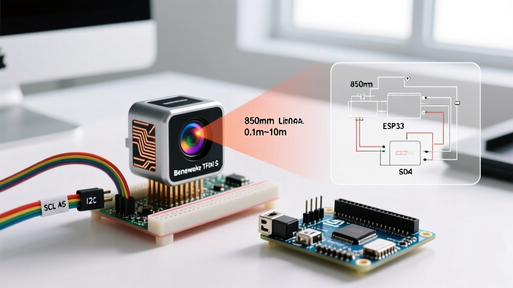
Unlike premium 940nm sensors (like the STMicroelectronics VL53L1X), the TFMini-S uses an 850nm laser. According to SparkFun's optical sensor integration guides, 850nm offers higher silicon responsivity, meaning the sensor can detect weaker reflections at longer distances (up to 12 meters). The trade-off? The sun emits massive amounts of 850nm infrared light. If your robot operates outdoors, solar saturation will cause the sensor to output a 'Signal Strength' error or lock at maximum range.
Navigating the Pinout and the JST-GH 1.25mm Trap
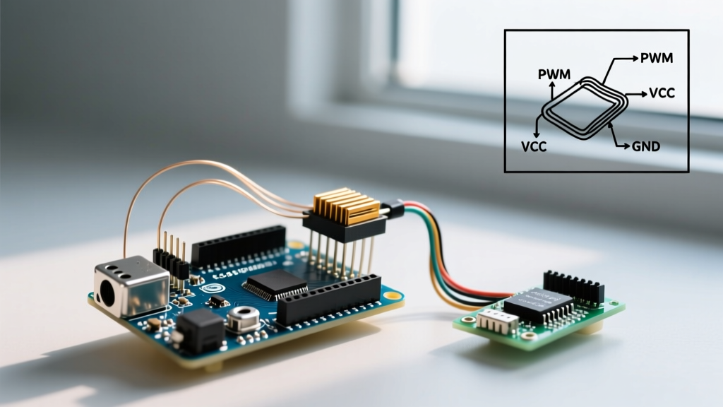
A common hardware failure mode occurs before the sensor is even powered on. The TFMini-S uses a JST-GH 1.25mm pitch connector. Many makers accidentally purchase 1.0mm pitch JST-SH pigtails, forcing them into the socket and permanently bending the internal crimp pins.
| Pin | Wire Color | Function (UART Mode) | Function (I2C Mode) |
|---|---|---|---|
| 1 | Red | 5V Power | 5V Power |
| 2 | Black | GND | GND |
| 3 | Green | TX | SDA |
| 4 | White | RX | SCL |
Note: The TFMini-S is 5V tolerant on its data lines, meaning you can connect it directly to an Arduino Uno (ATmega328P) without a logic level shifter. However, if you are using a 3.3V ESP32 or Raspberry Pi Pico, a bidirectional logic level converter is mandatory to prevent damaging the host microcontroller.
The Hidden I2C Configuration Command
Here is the most critical piece of information omitted from basic tutorials: The TFMini-S ships from the factory in UART mode by default. If you wire it to the Arduino I2C pins and run an I2C scanner sketch, it will not show up at its default address (0x10).
To switch the sensor to I2C mode, you must first wire it to the Arduino's hardware serial pins (TX/RX) and send a specific hex configuration command via the Serial Monitor:
Mode Switch Command:5A 04 0A 01 69
Send this 5-byte sequence at 115200 baud. The sensor will reply with5A 05 0A 01 00 6Ato confirm the switch. Once confirmed, power cycle the sensor, and it will now respond to I2C requests.
This permanent configuration step is detailed on page 14 of the Benewake datasheet, yet it remains the number one reason hobbyists abandon the lidar sensor arduino integration process.
Power Delivery: Why Your Arduino 5V Pin Might Fail
The datasheet specifies an operating voltage of 5V ±0.5V, with an average current draw of 140mA. However, it buries a crucial detail in the electrical characteristics section: Peak Current.
During the nanosecond laser pulse emission, the VCSEL driver circuit experiences transient current spikes up to 500mA. The onboard 5V linear regulator of an Arduino Uno is thermally limited and shares current with the ATmega chip and USB interface. Powering the TFMini-S directly from the Arduino's 5V pin often results in brownouts, causing the sensor to reboot mid-frame or output corrupted distance data (e.g., sudden jumps to 12,000mm).
The Fix: Power the TFMini-S using a dedicated 5V buck converter (like the Pololu D24V50F5) capable of delivering 1A+ continuous current, tying the ground back to the Arduino GND to maintain a common logic reference.
Arduino C++ Implementation (I2C Mode)
Once the sensor is in I2C mode, reading data requires requesting a 9-byte frame from the sensor's I2C address (0x10). The Arduino Wire Library handles the bus arbitration, but you must parse the frame manually to extract the distance and signal strength.
Here is the structural logic for your loop() function:
- Initiate
Wire.requestFrom(0x10, 9). - Verify the first byte is the frame header
0x59. - Read the next 8 bytes into an array.
- Calculate Distance:
(byte[2] << 8) | byte[1](Result in cm). - Calculate Signal Strength:
(byte[4] << 8) | byte[3]. - Verify the checksum (sum of first 8 bytes modulo 256 must equal byte[8]).
If the checksum fails, discard the frame. Environmental noise on the I2C bus can easily flip a bit, and relying on corrupted frames will cause your robot to crash into walls.
Real-World Edge Cases & Failure Modes
Even with perfect wiring and code, optical physics dictates that the TFMini-S will fail under specific environmental conditions. Understanding these edge cases separates amateur builds from robust engineering.
- The 10cm Blind Zone: Due to the physical separation between the TX laser and RX lens inside the tiny housing, the receiver cannot focus on the laser reflection if the object is closer than 10cm. The sensor will output a status code of '0' or hold the previous valid reading. Always mount the sensor at least 15cm from your robot's front bumper.
- Multi-Path Reflections on Glass: ToF sensors struggle with transparent or highly reflective angled surfaces. If the 850nm laser hits a glass window at a 45-degree angle, it will refract, bounce off a secondary wall, and return to the sensor. The calculated distance will be the total path length, resulting in 'ghost' obstacles.
- Low Reflectivity Targets: The datasheet notes a maximum range of 12 meters, but this assumes a target with >80% reflectivity (like white foam board). If you point the sensor at matte black rubber or dark asphalt (reflectivity <10%), the effective maximum range drops drastically to roughly 3 meters. Adjust your robot's braking algorithms based on the target material's albedo.
Final Thoughts on ToF Integration
Mastering the lidar sensor arduino workflow with the TFMini-S requires respecting both its digital protocols and its optical physics. By utilizing the correct JST-GH connectors, executing the hidden I2C configuration command, and providing clean, high-current 5V power, you unlock a highly reliable, 1000Hz distance measurement tool. For further reading on Time-of-Flight principles and optical limitations, refer to the Benewake official technical documentation to explore advanced register tweaking and baud rate customization.