
Why You Cannot Wire a DC Motor Directly to an Arduino
One of the most common mistakes beginners make when learning robotics is attempting to wire a DC motor directly to the digital GPIO pins of a microcontroller. While you might see a motor spin briefly on a workbench, this practice is a guaranteed way to destroy your board. The ATmega328P chip on an Arduino Uno R3 (and the Renesas RA4M1 on the Uno R4 Minima) has an absolute maximum current rating of 40mA per I/O pin, with a recommended safe operating limit of just 20mA.
In contrast, a standard 3V-6V TT gear motor draws roughly 150mA to 200mA under normal load, and can spike past 800mA during a stall condition. To safely control a DC motor with an Arduino, you must use a motor driver—an intermediary circuit that takes low-current logic signals from the microcontroller and switches high-current power from an external battery or power supply.
Choosing the Right Motor Driver (2026 Hardware Landscape)
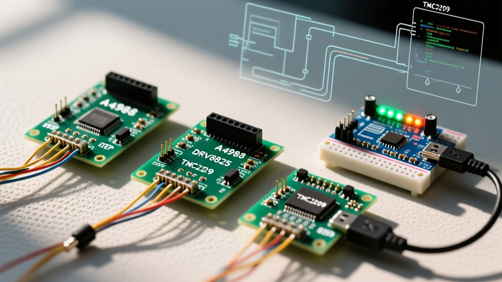
While the bipolar junction transistor (BJT) based L298N has been the default hobbyist choice for a decade, modern MOSFET-based drivers offer vastly superior efficiency. Below is a technical comparison of the three most common drivers used in DIY electronics today.
| Driver IC | Technology | Continuous Current | Voltage Drop | Avg. Price (2026) | Best Use Case |
|---|---|---|---|---|---|
| L298N | BJT H-Bridge | 2A per channel | ~2.0V | $4.00 - $6.00 | Basic learning, high-voltage (12V+) heavy motors |
| TB6612FNG | MOSFET H-Bridge | 1.2A per channel | ~0.5V | $6.00 - $9.00 | Battery-powered robots, 3V-6V TT motors |
| DRV8871 | N-Channel MOSFET | 3.6A | ~0.4V | $5.00 - $8.00 | Single high-torque motors, 12V-24V systems |
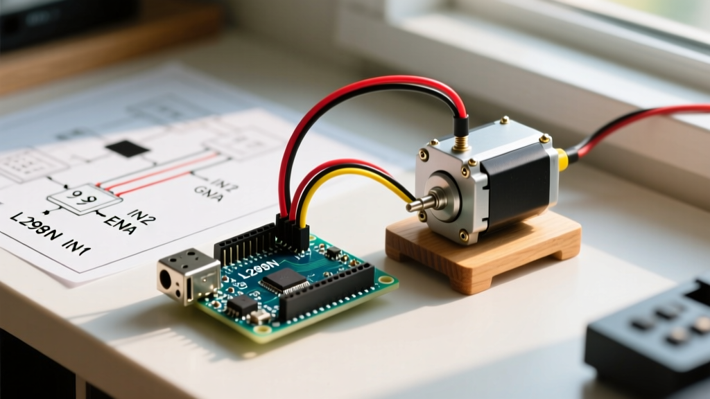
For this guide, we will focus on the L298N Dual H-Bridge module due to its ubiquity, robust screw terminals, and built-in 5V voltage regulator, which is highly convenient for powering the Arduino logic side in larger 12V projects. However, if you are building a low-voltage (5V) battery-operated robot, the L298N's 2V drop means your motor will only receive 3V, severely limiting torque. In that scenario, consult the SparkFun TB6612FNG Hookup Guide for a more efficient alternative.
Step-by-Step L298N Wiring Guide
Proper wiring is critical. A missing common ground or incorrect jumper configuration will result in erratic behavior or a fried driver. Here is the exact pinout mapping for controlling a single DC motor on Channel A.
1. Power Supply and Voltage Jumper Logic
The L298N module features a 3-pin block for power: 12V, GND, and 5V. It also has a 5V EN jumper cap.
- Scenario A (Motor Supply ≤ 12V): Connect your battery positive to
12Vand negative toGND. Leave the5V ENjumper ON. The module's onboard 7805 regulator will step down the voltage, allowing you to draw up to 500mA from the5Vpin to power your Arduino. - Scenario B (Motor Supply > 12V): Connect your battery positive to
12Vand negative toGND. Remove the5V ENjumper. You must supply 5V to the5Vpin from an external source (like the Arduino's 5V output) to power the L298N's logic chip. Exceeding 12V with the jumper on will destroy the 7805 regulator.
2. Control Pin Mapping
Connect the L298N logic pins to the Arduino Uno as follows:
- ENA: Connect to Arduino Pin 9 (Must be a PWM pin for speed control).
- IN1: Connect to Arduino Pin 8 (Digital).
- IN2: Connect to Arduino Pin 7 (Digital).
- GND: Connect to Arduino GND. Crucial: The Arduino and the motor driver must share a common ground, or the logic signals will not register correctly.
3. Motor Output
Connect your DC motor wires to OUT1 and OUT2 on the L298N. DC motors are non-polarized, so the direction of the wires here does not matter; you can reverse the motor direction via code by flipping IN1 and IN2.
Arduino Code for PWM Speed and Direction Control
To control a DC motor with an Arduino, we use digital writes for direction and Pulse Width Modulation (PWM) via the analogWrite() function for speed. On the Arduino Uno, pins 3, 9, 10, and 11 operate at a default PWM frequency of 490 Hz, while pins 5 and 6 operate at 980 Hz. We use Pin 9 (490 Hz) here, which is ideal for audible noise reduction in standard gear motors.
// Pin Definitions
const int enA = 9;   // PWM pin for speed
const int in1 = 8;   // Digital pin for direction
const int in2 = 7;   // Digital pin for direction

void setup() {
  pinMode(enA, OUTPUT);
  pinMode(in1, OUTPUT);
  pinMode(in2, OUTPUT);

  // Ensure motor is stopped on boot
  digitalWrite(in1, LOW);
  digitalWrite(in2, LOW);
  analogWrite(enA, 0);
}

void loop() {
  // 1. Spin Forward at 50% speed (PWM value ~127)
  setMotorSpeed(127, true);
  delay(2000);

  // 2. Stop the motor (Coast stop)
  setMotorSpeed(0, true);
  delay(1000);

  // 3. Spin Reverse at 100% speed (PWM value 255)
  setMotorSpeed(255, false);
  delay(2000);

  // 4. Active Brake (Shorts motor terminals for fast stopping)
  activeBrake();
  delay(3000);
}

// Function to set motor speed and direction
void setMotorSpeed(int speed, bool isForward) {
  speed = constrain(speed, 0, 255);

  if (isForward) {
    digitalWrite(in1, HIGH);
    digitalWrite(in2, LOW);
  } else {
    digitalWrite(in1, LOW);
    digitalWrite(in2, HIGH);
  }
  analogWrite(enA, speed);
}

// Function to apply an active brake
void activeBrake() {
  digitalWrite(in1, HIGH);
  digitalWrite(in2, HIGH);
  analogWrite(enA, 255);
}
Understanding the Active Brake
In the code above, the activeBrake() function sets both IN1 and IN2 HIGH simultaneously. This effectively shorts the motor's internal coils through the H-Bridge, generating counter-electromotive force (Back-EMF) that brings the motor to a rapid, screeching halt. This is vastly superior to simply setting the PWM to 0, which allows the motor to 'coast' to a stop due to inertia.
Real-World Troubleshooting and Edge Cases
Even with perfect wiring, motor control circuits introduce electrical noise and thermal challenges. Here is how to diagnose the most common failure modes encountered in the field.
Pro Tip: DC motors are notorious for generating electromagnetic interference (EMI). If your Arduino resets randomly when the motor starts, solder a 0.1μF ceramic capacitor directly across the motor's metal terminals to suppress high-frequency brush noise.
1. The Motor Twitches but Will Not Spin
Cause: Insufficient current delivery or a high-impedance connection. The L298N requires a minimum logic voltage of 4.5V to register a HIGH signal. If your Arduino is powered via a weak USB port, the 5V rail may sag. Furthermore, ensure you are using 18 AWG or thicker wire for the motor power supply; thin breadboard jumper wires (usually 24 AWG) will cause massive voltage drops under load.
2. The L298N Heatsink is Too Hot to Touch
Cause: Thermal throttling. The L298N uses BJT transistors which dissipate excess voltage as heat. At 2A continuous draw, the chip will dissipate roughly 4 Watts of heat. The stock aluminum heatsink is only rated for about 1.5W of passive dissipation. If the junction temperature exceeds 150°C, the IC's internal thermal shutdown circuit will trigger, cutting power to the motor. Solution: Upgrade to a MOSFET driver like the TI DRV8871 or add active cooling (a 5V fan).
3. PWM Speed Control is Non-Linear
Cause: DC motors have a minimum starting voltage threshold. A PWM value of 10 (out of 255) might not provide enough average voltage to overcome the motor's static friction. You will often find that the motor does nothing from PWM 0 to 60, then suddenly jumps to 30% speed at PWM 70. Solution: In your code, map your input range to the motor's effective range. For example, use the map(val, 0, 100, 70, 255) function to translate a 0-100% user input into the 70-255 PWM operating window.
Summary
Learning to properly control a DC motor with an Arduino bridges the gap between writing abstract code and interacting with the physical world. By respecting the current limits of your microcontroller, choosing the appropriate H-Bridge driver for your voltage requirements, and implementing active braking in your firmware, you can build robust, reliable electromechanical systems capable of handling real-world loads.