
The Challenge of Multi-Peripheral Expansion
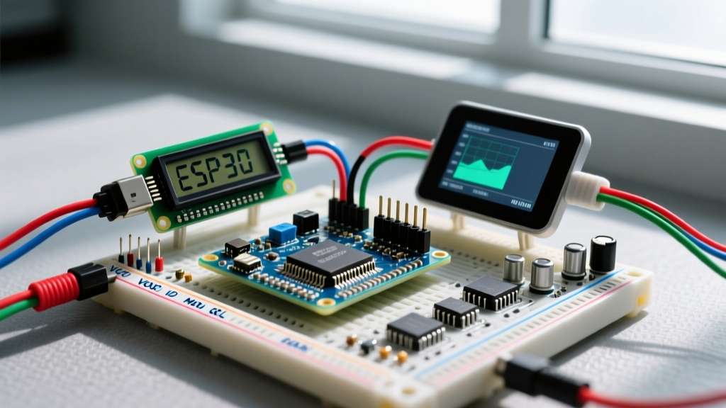
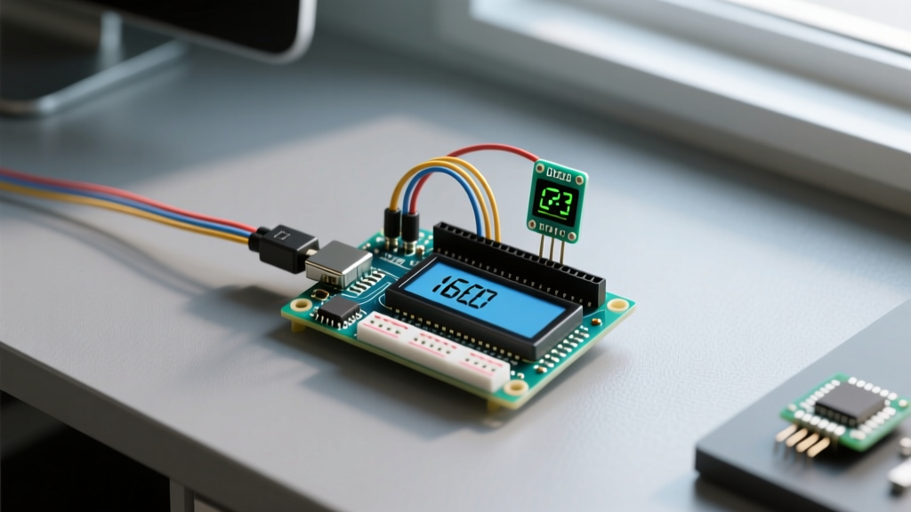
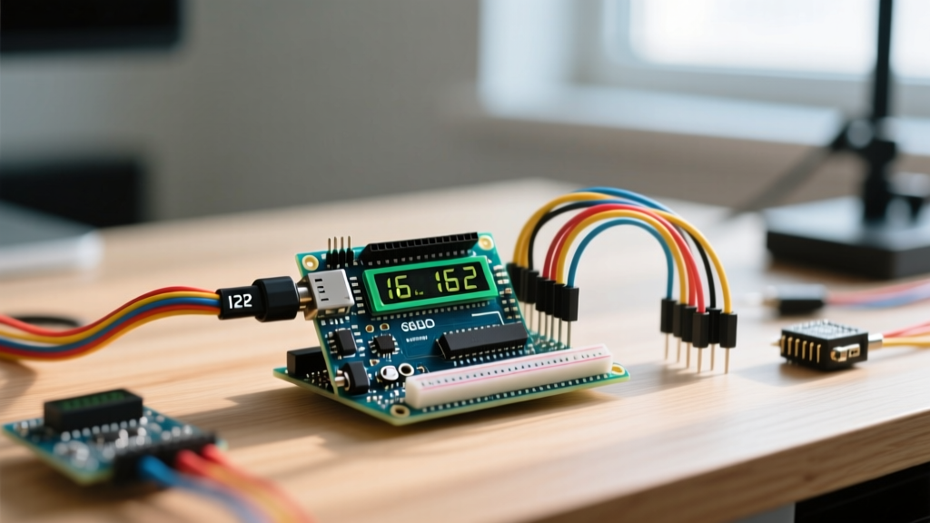
Integrating a visual interface into a crowded microcontroller breadboard is a rite of passage for hardware developers. When you move beyond blinking LEDs and start building environmental monitors or automated relays, adding a display LCD Arduino module becomes essential. However, slapping a standard 16x2 or 20x4 character LCD onto an Arduino Uno R3 or Nano alongside a BME280 environmental sensor, a DS3231 Real-Time Clock (RTC), and a 4-channel relay module introduces severe architectural bottlenecks. You are no longer just managing pins; you are managing I2C bus capacitance, power rail sag, and non-blocking execution timelines.
In 2026, while newer OLED and TFT displays dominate high-end consumer projects, the classic HD44780-compatible LCD with an I2C backpack remains the undisputed king of industrial prototyping and rugged DIY deployments due to its high contrast, low cost, and 5V tolerance. This guide dissects the exact hardware, electrical, and software strategies required to run an LCD alongside multiple I2C peripherals without crashing the bus or starving your sensors of current.
Power Budgeting: Why USB 5V Fails in Multi-Sensor Arrays
The most common point of failure in complex Arduino setups is not code; it is power starvation. The standard 16x2 LCD backlight consists of an array of white or blue LEDs that typically draw between 80mA and 160mA. When you combine this with an Arduino Uno R3 (which draws roughly 45mA at idle) and multiple active sensors, you quickly approach the limits of the onboard voltage regulator.
If you power your Arduino via the barrel jack or Vin pin with a 9V or 12V wall adapter, the onboard NCP1117 linear regulator must dissipate the excess voltage as heat. Drawing 300mA total from the 5V pin with a 12V input forces the regulator to burn over 2 watts of heat, leading to thermal shutdown within minutes.
Typical Multi-Peripheral Power Draw Matrix
| Component | Typical 5V Current Draw | Peak / Startup Surge |
|---|---|---|
| Arduino Uno R3 (ATmega328P) | 45 mA | 60 mA |
| 16x2 LCD (Blue Backlight) | 120 mA | 120 mA |
| BME280 Sensor Module | 1.5 mA | 2 mA |
| DS3231 RTC Module | 3 mA | 5 mA |
| 5V Relay Module (per coil) | 75 mA | 100 mA |
| Total (with 2 Relays) | 319.5 mA | 387 mA |
Expert Recommendation: For any multi-peripheral setup exceeding 250mA, bypass the Arduino's onboard regulator entirely. Use an external LM2596 buck converter module set precisely to 5.0V to feed the 5V rail directly, or power the LCD backlight separately via a dedicated transistor switch to allow software-controlled dimming and power saving.
Resolving I2C Address Collisions
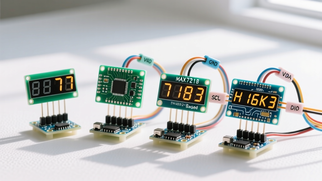
The I2C protocol relies on unique 7-bit addresses for every device on the bus. When integrating a display LCD Arduino setup, you will almost certainly encounter address collisions. Most inexpensive I2C LCD backpacks utilize the NXP PCF8574 or PCF8574A I/O expander chips. According to the official NXP PCF8574 datasheet, these two chips have entirely different base address blocks, which causes endless confusion for beginners.
- PCF8574T (Base 0x20): With A0, A1, and A2 pads un-soldered (pulled high via onboard resistors), the address is typically
0x27. - PCF8574AT (Base 0x38): With A0, A1, and A2 pads un-soldered, the address is typically
0x3F.
If your BME280 sensor and your LCD backpack share an address, the Arduino Wire library will send data to the wrong silicon, resulting in garbled text or frozen sensors. You must use an I2C scanner sketch to map your bus before writing your main application logic. For a comprehensive list of default peripheral addresses, consult the Adafruit I2C Address Master List.
Hardware Fix: If a collision occurs, use a soldering iron to bridge the A0, A1, or A2 pads on the back of the LCD's PCF8574 backpack. Bridging a pad pulls that pin to ground, altering the binary address sequence and freeing up the conflicting address space.
The Pull-Up Resistor Trap: Bus Capacitance and Signal Degradation
This is the silent killer of multi-peripheral I2C setups. The I2C specification requires pull-up resistors on the SDA and SCL lines to pull the bus high when devices release the line. Most breakout boards (including LCD backpacks, RTCs, and sensor modules) include onboard 4.7kΩ pull-up resistors.
When you wire four modules together in parallel, those 4.7kΩ resistors combine in parallel. The equivalent resistance drops to roughly 1.17kΩ. According to the Arduino Wire Library Reference and the ATmega328P datasheet, the microcontroller's I/O pins have a maximum sink current limit of 3mA to 20mA depending on the exact operating conditions. A 1.17kΩ pull-up on a 5V line demands over 4.2mA every time the pin pulls the bus LOW. While this might not instantly destroy the ATmega, it drastically increases the rise time of the I2C signals due to bus capacitance, leading to corrupted bytes, random LCD characters, and sensor timeouts.
Pro-Tip: If your I2C bus has more than three modules, use a multimeter to measure the resistance between the SDA line and 5V. If it reads below 2.5kΩ, use a hobby knife to scratch the copper trace and disconnect the pull-up resistors on all but one master module, or add a dedicated I2C bus extender like the PCA9600.
Non-Blocking Code Architecture for Smooth Display Updates
In a multi-sensor environment, using the delay() function is catastrophic. Reading a BME280 takes roughly 15 milliseconds; updating an LCD via I2C takes roughly 10 to 20 milliseconds per string. If you use delays, your relay control loops or button debouncing routines will stall, causing missed events.
You must implement a state-machine approach using millis() to decouple your sensor polling from your display refresh rate. The human eye only requires a 15Hz refresh rate to perceive smooth motion, but sensor data rarely changes faster than once per second.
#include <Wire.h>
#include <LiquidCrystal_I2C.h>

LiquidCrystal_I2C lcd(0x27, 16, 2);
unsigned long lastDisplayUpdate = 0;
const long displayInterval = 500; // Update LCD every 500ms

void setup() {
  Wire.begin();
  lcd.init();
  lcd.backlight();
}

void loop() {
  // 1. Handle time-critical sensor reads and relay logic here (Non-blocking)
  handleSensors();

  // 2. Update Display on independent timer
  unsigned long currentMillis = millis();
  if (currentMillis - lastDisplayUpdate >= displayInterval) {
    lastDisplayUpdate = currentMillis;
    updateLCD();
  }
}

void updateLCD() {
  lcd.setCursor(0, 0);
  lcd.print("Temp: 24.5 C    ");
  lcd.setCursor(0, 1);
  lcd.print("Hum:  45 %      ");
}
By padding your strings with empty spaces (e.g., "C "), you overwrite leftover characters from previous longer strings, eliminating the need to call lcd.clear(), which is notoriously slow and causes visible screen flickering.
Real-World Troubleshooting and Edge Cases
1. The Contrast Potentiometer
Almost every I2C LCD backpack features a small blue trimmer potentiometer on the rear. Out of the box, these are often set to the extreme ends of the resistance spectrum. If your backlight is on but the screen is blank, or if you see a row of solid white blocks, use a small Phillips screwdriver to turn the potentiometer. The optimal viewing angle usually sits around the 40% to 60% rotation mark.
2. Long Wire Runs and Ghosting
I2C was designed for on-board communication, typically limited to 30 centimeters. If your LCD is mounted on an enclosure door while the Arduino sits in the back panel, the extended SDA/SCL wires act as antennas, picking up electromagnetic interference (EMI) from nearby relays or AC mains wiring. This results in 'ghosting' (random characters appearing) or the LCD freezing entirely. Always use twisted-pair cabling for SDA/SCL lines, and keep them physically separated from relay switching wires.
3. Component Sourcing in 2026
When purchasing LCD modules, avoid unbranded 'random color' listings. Standardize on the DFRobot I2C 16x2 LCD (SKU: DFR0063) or the Adafruit Character LCD Backpack (Product ID: 292). While slightly more expensive (typically $12 to $18 USD compared to $3 generic clones), they feature robust PCF8574 implementations, properly rated contrast potentiometers, and consistent pin mappings that will save you hours of debugging conflicting library forks.